Submerged power generating apparatus

a technology of power generation apparatus and submerged water, which is applied in the direction of water power plants, artificial islands, tidal stream/damless hydropower, etc., can solve the problems of high cost of production and maintenance of tidal power generation devices, and the need for complicated and expensive slip ring arrangements, etc., to achieve the effect of increasing the strength of the apparatus

Active Publication Date: 2008-10-28
SOIL MACHINE DYNAMICS
View PDF15 Cites 27 Cited by
  • Summary
  • Abstract
  • Description
  • Claims
  • Application Information

AI Technical Summary

Benefits of technology

[0021]This provides the advantage of in

Problems solved by technology

In particular, in the case of tidal power due to the generally hazardous and aggressive nature of the sea, the costs of production and maintenance of tidal power generation devices are high.
This type of device suffers from the drawback that as a result of the turbine's strong tendency to align itself with the direction of water flow such that the turbine blades rotate about a generally horizontal axis relative to the turbine body (in order to maximise the efficiency of the turbine), movement of the turbine from

Method used


Image

  • Submerged power generating apparatus
  • Submerged power generating apparatus
  • Submerged power generating apparatus

Examples


Embodiment Construction

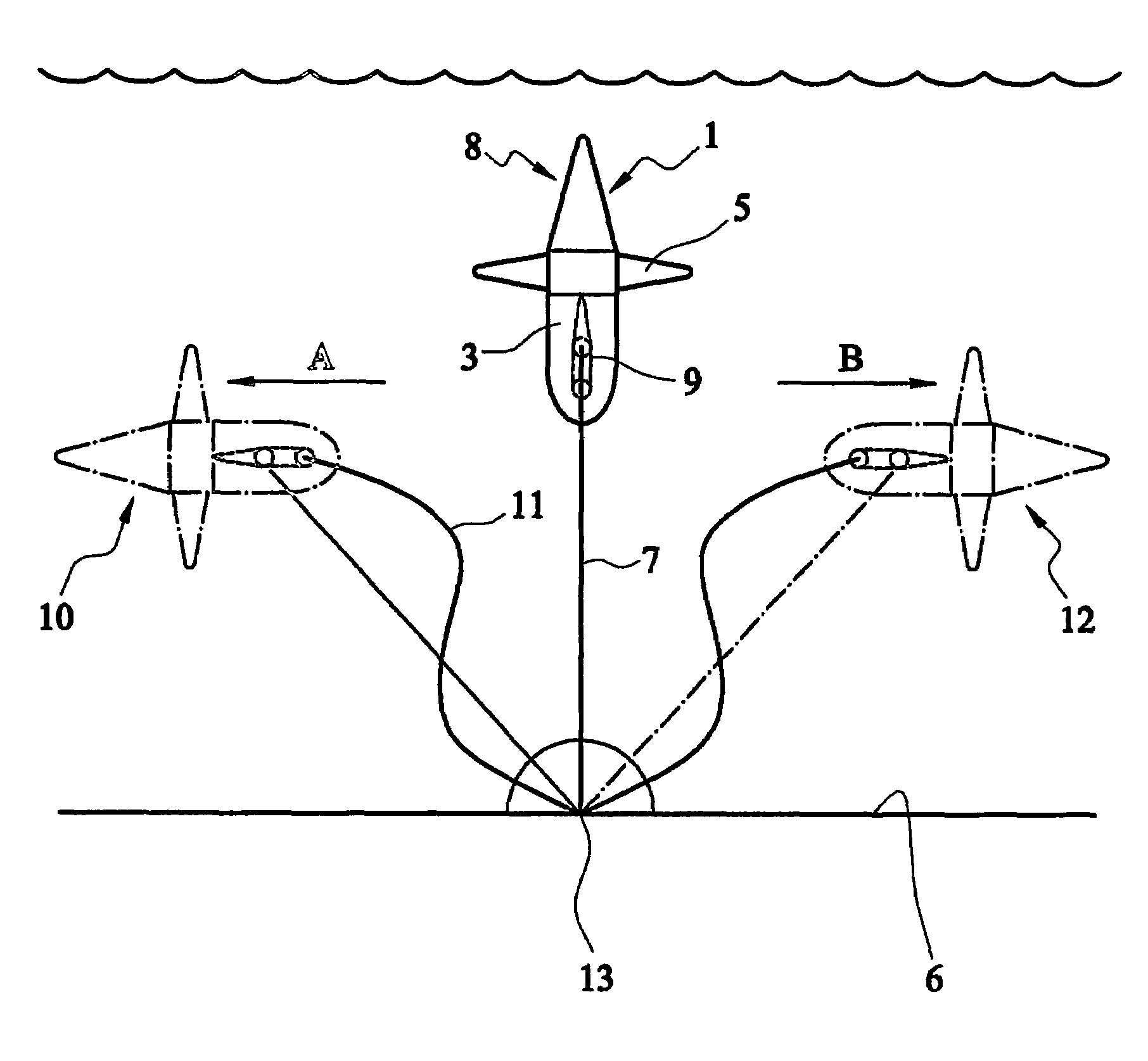
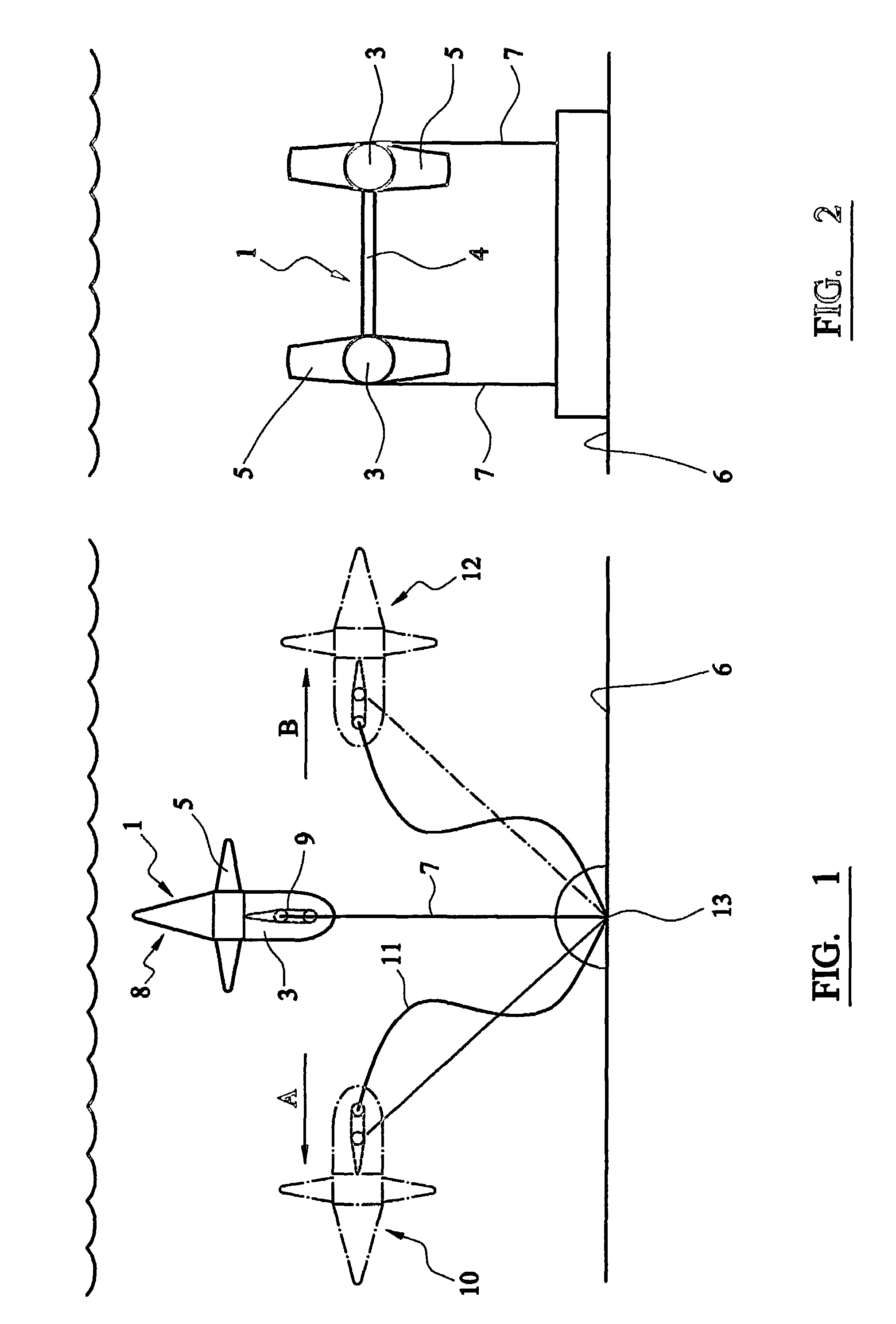
[0028]Referring to FIGS. 1 and 2, an undersea power generation apparatus 1 comprises two turbines 3 mounted side by side at either side of a support strut 4 of hydrofoil-shaped cross section. Each turbine 3 has a set of turbine blades 5, which in the embodiment shown in FIG. 2 counter rotate so as to cancel out the respective torque produced by each turbine. The apparatus 1 is pivotally interconnected at point 9 to a pair of mooring cables 7, which are moored to the seabed 6.

[0029]The turbines 3 are positively buoyant such that in zero current they point vertically upwards as denoted by 8. When the current flows in the direction shown by arrow A, the drag forces on turbines 3 and support strut 4 cause the power generation apparatus 1 to pivot about pivot point 9 and pitch over into the condition denoted by 10 and shown in broken lines.

[0030]In this position the force of water flowing past the turbines 3 causes the turbine blades 5 to rotate and thus produce electricity in an electri...


PUM


Abstract

An undersea power generation apparatus (1) includes two turbines (3) mounted side by side at either side of a support strut of hydrofoil-shaped cross section, each turbine (3) having a set of turbine blades which counter rotate so as to cancel out the respective torque produced by each turbine. The apparatus (1) is pivotally interconnected at point (9) to a pair of mooring cables (7), which are releasably moored to the seabed (6). The turbines (3) are positively buoyant such that in zero current they point vertically upwards as denoted by (8). When the current flows in the direction shown by arrow A, the drag forces on turbines (3) and support strut cause the apparatus (1) to pivot about point (9) and pitch over into condition denoted by (10) and shown in broken lines.

Description

BACKGROUND OF THE INVENTION[0001]1. Field of the Invention[0002]The present invention relates to apparatus for generating electrical power from water flow, and relates particularly, but not exclusively to generating electricity from tidal flow.[0003]2. Description of Related Art[0004]In order to make sources of renewable energy economically viable, the costs of electricity production from renewable energy sources have to be minimised. In particular, in the case of tidal power due to the generally hazardous and aggressive nature of the sea, the costs of production and maintenance of tidal power generation devices are high.[0005]Prior art tidal power generation devices rely on a turbine to align itself with tidal current by rotating around a vertical axis through a mooring point, or by rotating a pillar or other such fixing device. This type of device suffers from the drawback that as a result of the turbine's strong tendency to align itself with the direction of water flow such that ...

Claims


Application Information

Patent Timeline
IPC IPC(8): E02B9/00F03B13/10F03B13/26F03B17/06
CPCF03B13/10F03B13/264F03B17/061E02B2017/0091Y02E10/28Y02E10/38Y02E10/30Y02E10/20
Inventor MANCHESTER, JONATHAN RALPH
Owner SOIL MACHINE DYNAMICS
Why Eureka
Try Eureka