Motor of rotor with built-in permanent magnet

a technology of permanent magnets and motors, which is applied in the direction of magnetic circuit rotating parts, dynamo-electric machines, and magnetic circuit shape/form/construction, etc., can solve the problems of low manufacturing cost, inconvenient to electrical vehicles and compressors of refrigeration and air conditioning fields, and traditional motor torque of surface mount motors

Inactive Publication Date: 2006-01-17
IND TECH RES INST
View PDF6 Cites 20 Cited by
  • Summary
  • Abstract
  • Description
  • Claims
  • Application Information

AI Technical Summary

Benefits of technology

[0009]The first object of the present invention is to offer a motor of rotor with built-in permanent magnet, and the motor is with low cogging torque to be sure of that the functions of promoting running efficiency and lowering vibration noise are working properly.
[0010]The second object of the present invention is to offer a motor of rotor with built-in permanent magnet, the motor is easily and flexibly designed and formed, thus the cost is certainly down.

Problems solved by technology

The design of traditional motor torque of surface mount motor (T=Pn×φa×Ia, where Pn is pole number, φa is magnetic flux on d-axis, Ia is electric current on d-axis) is not suitable to electrical vehicles and compressors of refrigeration and air condition fields.
Four rectangular piece permanent magnets 22 are easily made and thus manufacturing cost is lower, but the arrangement causes serious magnetic flux leakage and cogging phenomena.
Flux leakage lowers down effective torque and motor efficiency.
Cogging phenomena increases motor cogging torque, and vibration and noise are both increased as well.
Obviously, motor assembly becomes very complicated.
Although the design highly decreases magnetic flux leakage and promotes output torque, the arc curvature of arc piece permanent magnet 24 is complicate, and it is not easily formed in manufacturing.

Method used


Image

  • Motor of rotor with built-in permanent magnet
  • Motor of rotor with built-in permanent magnet
  • Motor of rotor with built-in permanent magnet

Examples


Embodiment Construction

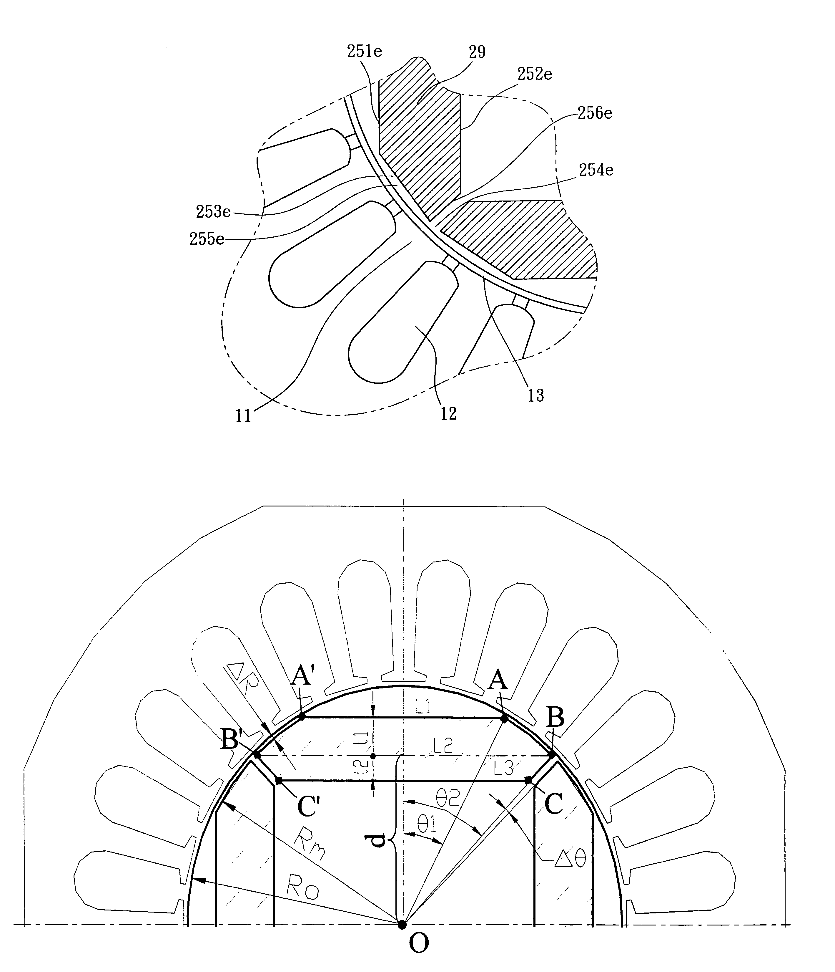
[0038]The main features of motor of rotor with built-in permanent magnet are: a plurality of nearly rectangular-shaped openings are formed surrounding a outer-skirt of a rotor core; each opening is formed with the same shape as the rectangular permanent magnet; each opening is with two parallel surfaces, namely a top surface and a bottom surface, and each of them is a flat plate figure; the top surface is adjacent to a outer contour of rotor core and extends along the contour so as to form a side surface substantially parallel to and nearby the outer contour of the rotor core; two adjacent side surfaces are spaced-apart with a certain width of a channel. Based on the design, manufacturing cost and motor cogging torque can be lowered down; on the other hand, output torque is increased.

[0039]Please refer to FIGS. 3A and 3B, which are 3-D structure views of the two preferred embodiments of rotor with built-in permanent magnet of the present invention. Wherein, the rotor 2 with built-in...


PUM


Abstract

The present invention is a motor of rotor with built-in permanent magnet, which includes an annular stator and a rotor. The annular stator has a cylindrical interior into which the rotor is inserted. A space is formed between a circumference surface of cylindrical interior and rotor. The rotor further includes a rotor core, and a plurality of openings are formed surrounding the rotor core. Each opening is with two parallel surfaces, a top surface and a bottom surface, and each of them is a flat plate figure. A suitable distance is between two side surfaces and an outer circumference of the rotor, and the two side surfaces of adjacent openings are spaced by a channel fo suitable width. A plurality of permanent magnets are arranged in openings by way of interlaced magnetic poles, and the shape of permanent matches the shape of the opening.

Description

RELATED APPLICATIONS[0001]This application is a continuation-in-part of U.S. Ser. No. 10 / 036,504, filed on Jan. 7, 2002, entitled “A Motor of Rotor With Built-In Permanent Magnet” and now abandoned.BACKGROUND OF THE INVENTION[0002]1. Field of the Invention[0003]The present invention is a motor of rotor with built-in permanent magnet, especially refer to a rotor which has no flux-barrier holes, and can effectively prevent phenomena of short-circuiting of magnetic flux.[0004]2. Background of the Invention[0005]As science is advanced day by day, the needs of normal life tend to short, light, thin and small products; the improvement of general mechanical mechanism is toward to high efficiency. The design of traditional motor torque of surface mount motor (T=Pn×φa×Ia, where Pn is pole number, φa is magnetic flux on d-axis, Ia is electric current on d-axis) is not suitable to electrical vehicles and compressors of refrigeration and air condition fields. Thus, adding an permanent magnet on...

Claims


Application Information

Patent Timeline
Patent Type & Authority Patents(United States)
IPC IPC(8): H02K21/12H02K1/27H02K21/14H02K29/03
CPCH02K1/276H02K29/03H02K21/14
Inventor CHANG, YU-CHOUNGLAI, CHING-FENGTSENG, CHING-HUAN
Owner IND TECH RES INST
Why Eureka
Try Eureka