Brushless permanent magnet motor

a permanent magnet motor and brushless technology, applied in the field of actuators, can solve the problems of inability to achieve desired saliency and difficulty in meeting both of these requirements for many current brushless permanent magnet motors, and achieve the effects of low cogging torque, high saliency, and increased the number of magnetic stator poles

Inactive Publication Date: 2014-08-07
JOHNSON ELECTRIC SA
View PDF9 Cites 5 Cited by
  • Summary
  • Abstract
  • Description
  • Claims
  • Application Information

AI Technical Summary

Benefits of technology

[0005]Some embodiments are directed at a brushless permanent magnet electric motor configured to have high saliency and low cogging torque. The brushless permanent magnet electric motor comprises a stator having a plurality of stator teeth defining a plurality of winding slots, and a rotor having a permanent magnet defining a plurality of magnetic poles configured to rotate relative to the stator. In some embodiments, each of the stator teeth contains a pole head with a plurality of grooves. The grooves are configured to be substantially parallel to the axial direction of the motor, and function to increase the number of magnetic stator poles of the motor, thereby lowering cogging torque without lowering saliency. In some embodiments, the permanent magnet is substantially annular, and contains a plurality of notches on one side positioned between adjacent pairs of magnetic poles. The notches are configured to increase the coefficient of pole arc or pole embrace of the rotor, in order to decrease the cogging torque of the motor.

Problems solved by technology

At the same time, it is desirable for the cogging torque of the motor to be small because high cogging torque would create undesirable vibration and noise during motor operation.
Satisfying both of these requirements is difficult for many current brushless permanent magnet motors.
However, due to the number of slots being close to the number of poles, the desired saliency cannot be achieved.

Method used


Image

  • Brushless permanent magnet motor
  • Brushless permanent magnet motor
  • Brushless permanent magnet motor

Examples


Embodiment Construction

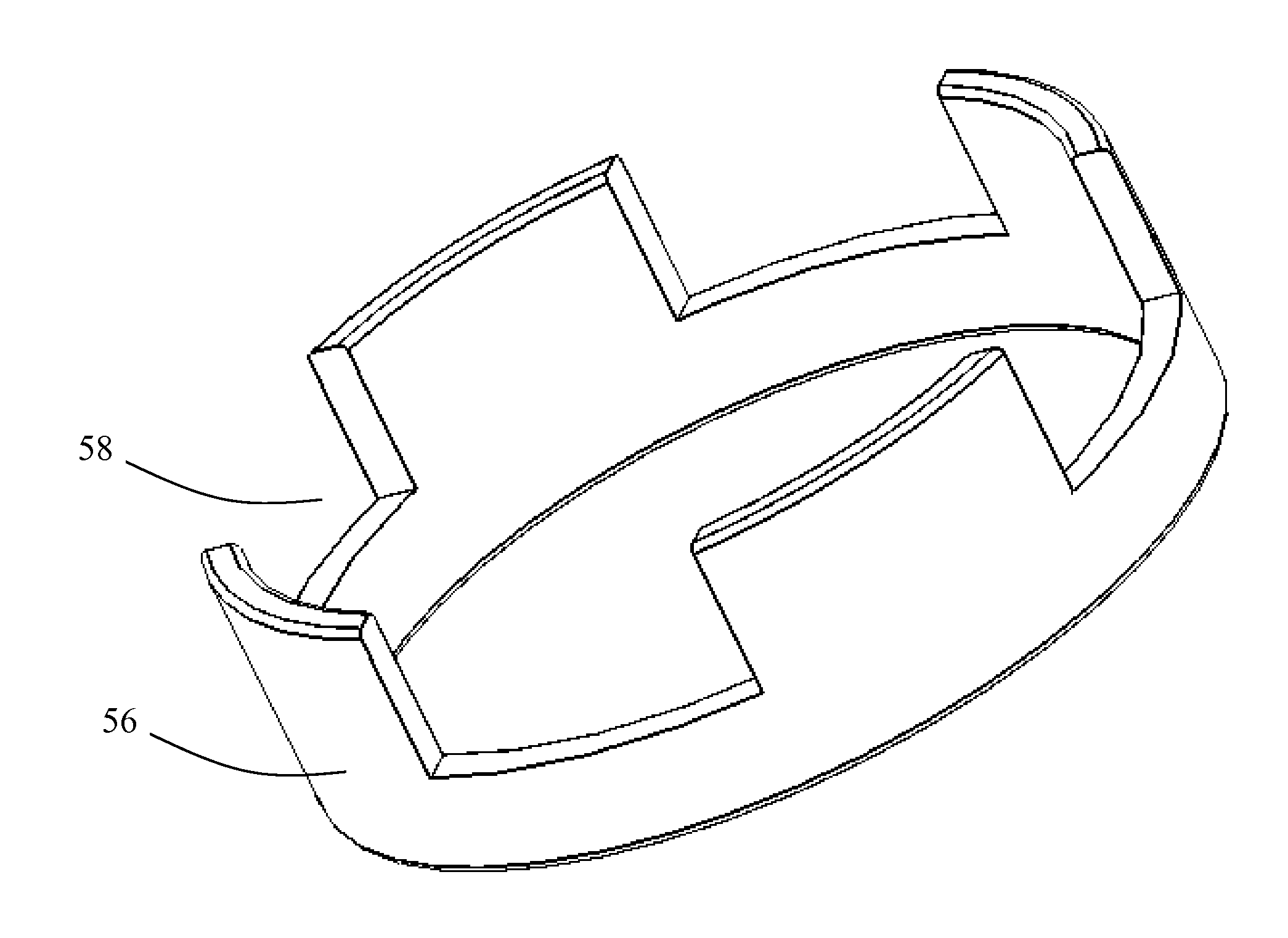
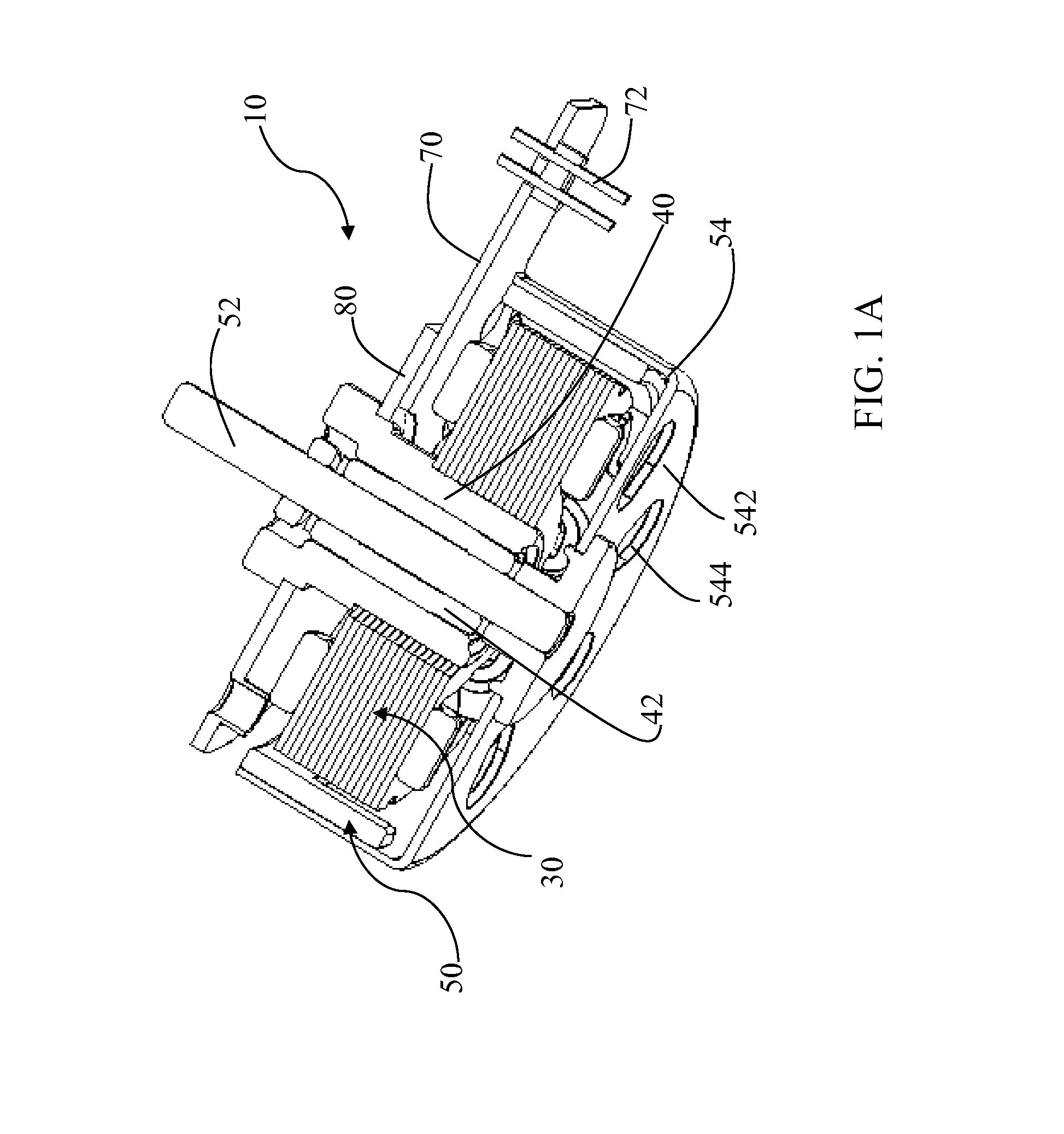
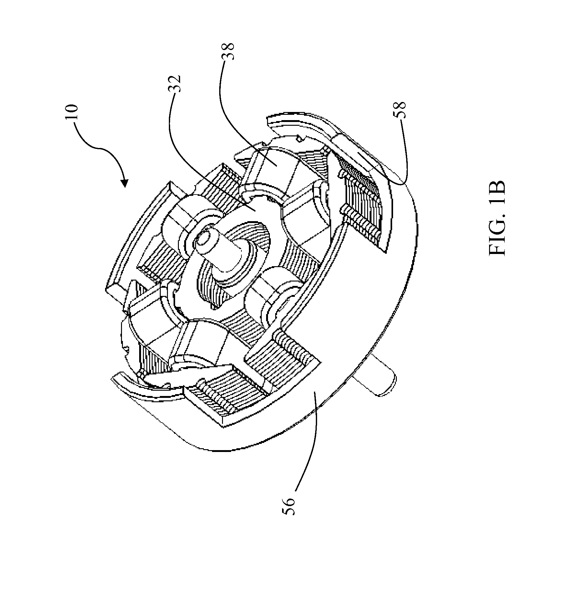
[0010]Various features are described hereinafter with reference to the figures. It shall be noted that the figures are not drawn to scale, and that the elements of similar structures or functions are represented by like reference numerals throughout the figures. It shall also be noted that the figures are only intended to facilitate the description of the features for illustration and explanation purposes, unless otherwise specifically recited in one or more specific embodiments or claimed in one or more specific claims. The drawings figures and various embodiments described herein are not intended as an exhaustive illustration or description of various other embodiments or as a limitation on the scope of the claims or the scope of some other embodiments that are apparent to one of ordinary skills in the art in view of the embodiments described in the Application. In addition, an illustrated embodiment need not have all the aspects or advantages shown.

[0011]An aspect or an advantage...


PUM


Abstract

A brushless permanent magnet electric motor (10) configured to have high saliency and low cogging torque, comprises a stator (30) having a plurality of stator teeth (36), and a rotor (50) having a permanent magnet (56) having a plurality of magnetic poles. The stator teeth (36) contain pole heads (37) having grooves (39) substantially parallel to the axial direction of the motor (10) formed thereon, which function to increase the number of magnetic stator poles of the motor (10), increasing saliency. The permanent magnet (56) contains a plurality of notches (58) on one side positioned between the plurality of magnetic poles, configured to decrease the coefficient of pole arc of the rotor (50), thereby decreasing cogging torque.

Description

CROSS REFERENCE TO RELATED APPLICATION(S)[0001]This application claims the benefit of Chinese patent application serial no. 201310043646.3, filed on Feb. 4, 2013. The entire content of the aforementioned patent application is hereby incorporated by reference for all purposes.BACKGROUND[0002]Many existing actuators typically comprise a brushless permanent magnet motor using a Hall Effect sensor for detecting the positions of the permanent magnet. The desire to decrease material costs has spurred the development in the industry towards brushless permanent magnet motors without a Hall Effect sensor. In order to better detect the position of the actuator, it is generally desirable for the difference in inductance between the motor stator windings (the ratio between the maximum inductance and minimum inductance of the stator windings), or saliency, to be large. At the same time, it is desirable for the cogging torque of the motor to be small because high cogging torque would create undes...

Claims


Application Information

Patent Timeline
Patent Type & Authority Applications(United States)
IPC IPC(8): H02K1/27
CPCH02K1/2793H02K29/03H02K1/2795H02K1/279
Inventor KWAN, WAI LUN ALLANCHAI, JIEZHANG, TAOTAO, JINGPING
Owner JOHNSON ELECTRIC SA
Why Eureka
Try Eureka