Rotary structure of permanent magnet electric machinery and method for determining the structure thereof

a permanent magnet electric machinery and rotary structure technology, applied in the direction of dynamo-electric machines, electrical apparatus, magnetic circuits, etc., can solve the problems of affecting the operation of the electric machine, so as to achieve low cogging torque, low windage loss, and high air heat radiation

Inactive Publication Date: 2010-11-23
DELTA ELECTRONICS INC
View PDF3 Cites 2 Cited by
  • Summary
  • Abstract
  • Description
  • Claims
  • Application Information

AI Technical Summary

Benefits of technology

[0014]It is therefore an aspect of the present invention to provide a rotary structure of a permanent magnet electric machine and a method for determining the structure thereof. The rotary structure includes an inner stator and an outer rotor. The outer surface of the inner stator has K salient teeth for forming K winding slots. The inner surface of the outer rotor has P pairs of permanent magnets. A pair of inclined surfaces is formed on two sides of each permanent magnet along a peripheral direction and is symmetric with respect to a radial plane of the each permanent magnet. The inclined angle of the pair of inclined surfaces is determined by measuring variance profiles varying with the inclined angle for a windage loss, a temperature of the electric machine, an air flow rate, an electric loss and a cogging torque so as to accomplish effects of a low windage loss, a high air heat radiation, and a low cogging torque.
[0016]Each permanent magnet having two sides along a peripheral direction of the rotor includes a pair of inclined surfaces on the two sides. The pair of inclined surfaces is symmetric with respect to a radial plane of the each permanent magnet. An inclined angle α between the inclined surface and the radial plane is selected from a range of 90(1−1 / (4P))<α<90(1+1 / (4P)) for decreasing a cogging torque and a windage loss and increasing air heat radiation.

Problems solved by technology

The problem caused by the cogging torque is that the cogging torque results in the fluctuation of an output torque, influences the rotation thereof, and produces a speed fluctuation, vibration and noise.
At the same time, losses such as copper loss and core loss in the interior of the electric machine can make the iron core, the windings and the permanent magnets heated, thereby causing the temperature of the electric machine to rise.
In general, the air gap cannot be too thick so that the effect of air heat radiation is confined, thereby making the temperature of the electric machine too high.

Method used


Image

  • Rotary structure of permanent magnet electric machinery and method for determining the structure thereof
  • Rotary structure of permanent magnet electric machinery and method for determining the structure thereof
  • Rotary structure of permanent magnet electric machinery and method for determining the structure thereof

Examples


first embodiment

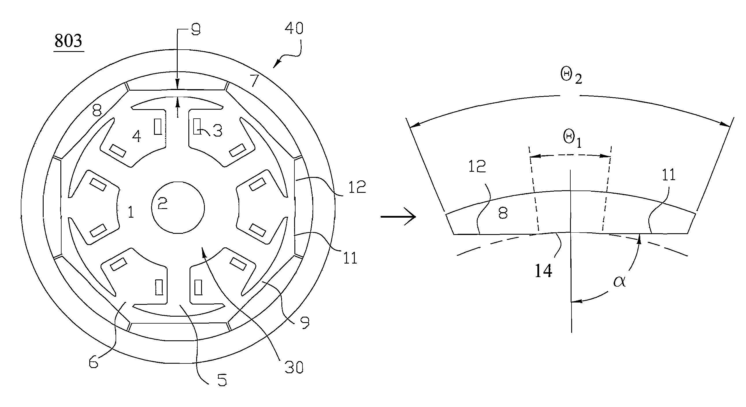
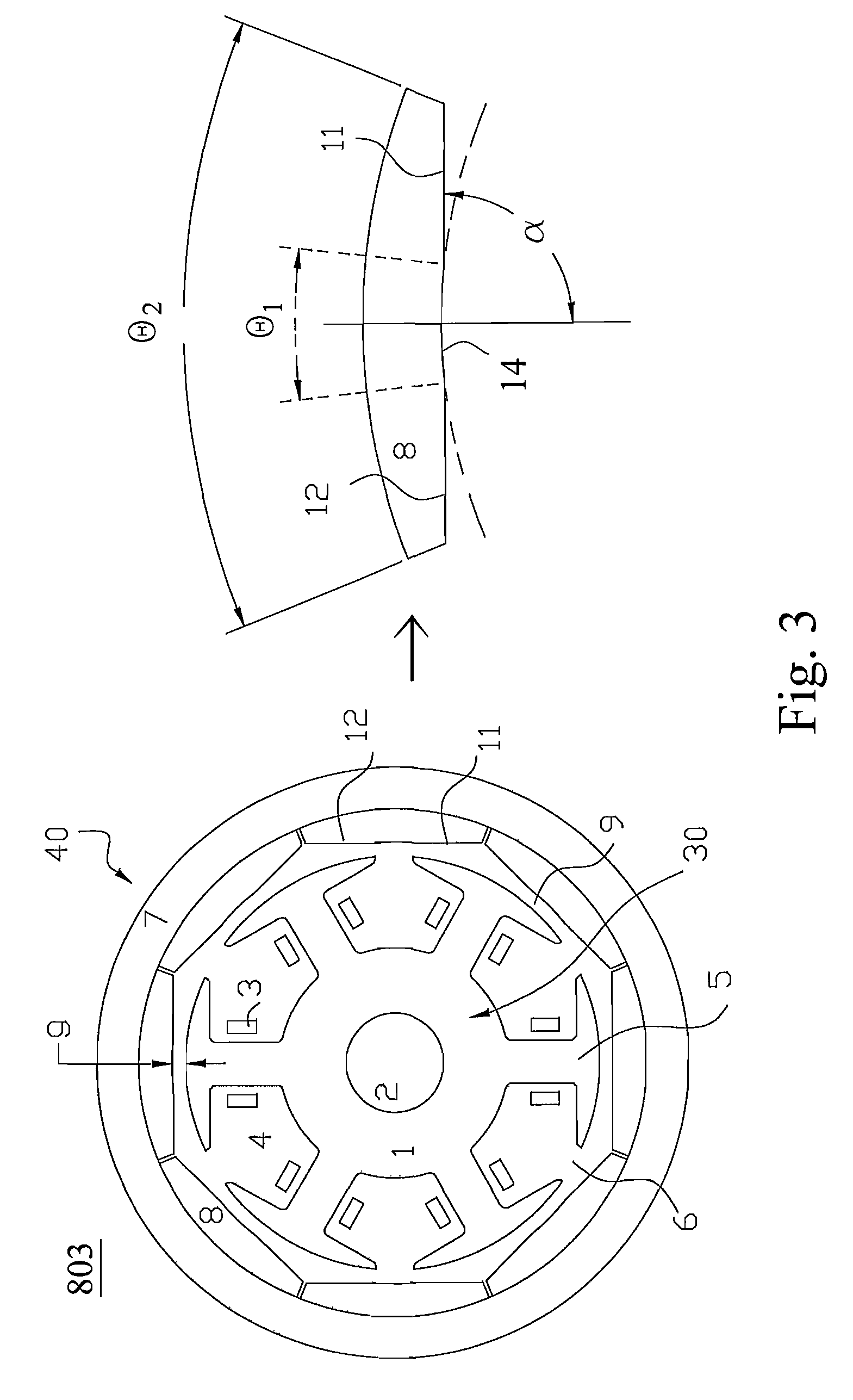
[0032]Please refer to FIG. 3, which is a cross-section diagram showing a rotary structure of a permanent magnet electric machine according to the present invention. The rotary structure 803 of the permanent magnet electric machine in FIG. 3 is obtained based on that in FIG. 1 and the features for decreasing a cogging torque are further incorporated thereinto. The rotary structure 803 is a permanent magnet motor having eight poles and six slots but is not limited to the permanent magnet motor, so that a similar structure is also applied to a permanent magnet generator. The rotary structure 803 includes a stator 30 and a rotor 40. A cylindrical shape stator 30 on which a rotating magnetic field is produced is fixed in the interior of the permanent magnet electric machine. The rotor 40 having a rotor magnetic field is annular in shape, coaxial with the stator 30, and around the stator 30. When the rotor magnetic field is interacted with the rotating magnetic field, the rotor 40 makes i...

second embodiment

[0049]Please refer to FIG. 12, which is a cross-section diagram showing a rotary structure of a permanent magnet electric machine according to the present invention. The rotary structure 812 of a permanent magnet electric machine in FIG. 12 is another permanent magnet motor having eight poles and six slots. Except inclined surfaces 11 and 12 of the permanent magnet 8 and middle planes, the definitions and symbols of respective components for the rotary structure 812 of the present embodiment are the same as those for the embodiment shown in FIG. 3. The feature of the present embodiment lies in that the middle of an inward surface of each permanent magnet forms a middle plane 15 for replacing the arc surface 14 in FIG. 3 and that inclined surfaces 11 and 12 are formed on two sides of the middle plane 15. Besides aforementioned advantages, such structure of the permanent magnet 8 also has advantages of convenient processing and saving material of permanent magnets and so on.

third embodiment

[0050]Please refer to FIG. 13, which is a cross-section diagram showing a rotary structure of a permanent magnet electric machine according to the present invention. The rotary structure 813 of the permanent magnet electric machine in FIG. 13 is the third permanent magnet motor having eight poles and six slots. Except inclined surfaces 11 and 12 of the permanent magnet 8, the definitions and symbols of respective components for the rotary structure 812 of the present embodiment are the same as those for the embodiment shown in FIG. 3. The feature of the present embodiment lies in that the inclined surfaces 11 and 12 are coplanar and the inclined angle α is 90 degrees. Besides aforementioned advantages, such structure of the permanent magnet 8 also has advantages of convenient processing and saving material of permanent magnets and so on.

[0051]According to the main feature of the present invention, each permanent magnet having two sides along a peripheral direction of the rotor inclu...


PUM


Abstract

A rotary structure of a permanent magnet electric machine including a stator and a rotor is provided. The stator has K salient teeth peripherally spaced with equal intervals for forming K winding slots, wherein K is a natural number greater than 1. The rotor has an annular inner surface and has P pairs of permanent magnets peripherally spaced with equal intervals along the inner surface for rotating around the stator, wherein P is a natural number. Each permanent magnet having two sides along a peripheral direction of the rotor includes a pair of inclined surfaces on the two sides, the pair of inclined surfaces is symmetric with respect to a radial plane of the each permanent magnet, and an inclined angle α between the inclined surface and the radial plane is selected from a range of 90(1−1 / (4P))<α<90(1+1 / (4P)).

Description

FIELD OF THE INVENTION[0001]The present invention relates to a rotary structure of permanent magnet electric machinery and a method for determining the structure thereof, and more particularly to a rotary structure of permanent magnet electric machinery for decreasing the cogging torque and the windage loss and increasing air heat radiation.BACKGROUND OF THE INVENTION[0002]Advantages of a permanent magnet electric machine include simple structure, reliable running, small size, lightness, little loss, high efficiency, and that its shape and dimension can be easily varied, so that it is applied to many fields which spread almost all over the daily life, agriculture, aviation, aerospace, national defense, and general industries.[0003]Please refer to FIG. 1, which is a cross-section diagram showing a rotary structure of a conventional permanent magnet electric machine having an outer rotor. In FIG. 1, a permanent magnet motor having eight poles and six slots is used as an example to des...

Claims


Application Information

Patent Timeline
Patent Type & Authority Patents(United States)
IPC IPC(8): H02K21/12
CPCH02K1/2786H02K21/16H02K1/2791
Inventor HUANG, SHIH-MINGHUANG, WEN-SHIWU, LI-JIANJIN, WAN-BINGYING, JIAN-PING
Owner DELTA ELECTRONICS INC
Why Eureka
Try Eureka