Method for manufacturing cooler for semiconductor-module, cooler for semiconductor-module, semiconductor-module and electrically-driven vehicle

a manufacturing method and semiconductor technology, applied in vehicle sub-unit features, applications, lighting and heating apparatus, etc., can solve the problems of increasing the load of the cooling pump that circulates the coolant, increasing the loss of coolant, and affecting the cooling effect of the cooling pump, so as to reduce the number of parts and reduce the manufacturing cost. , the effect of simple manufacturing process

Active Publication Date: 2016-05-12
FUJI ELECTRIC CO LTD
View PDF10 Cites 32 Cited by
  • Summary
  • Abstract
  • Description
  • Claims
  • Application Information

AI Technical Summary

Benefits of technology

[0028]According to the method for manufacturing a semiconductor-module cooler of the present invention, the method includes the step of fixing the flow rate control plate to the heat sink. Accordingly, the number of parts can be decreased, and the semiconductor-module cooler can be manufactured in a simple manufacturing process, thus decreasing the manufacturing cost. Moreover, the flow rate control plate is located in the boundary between the cooling channel and the coolant extraction channel. This prevents the coolant from flowing thorough a certain channel of the heat sink with a higher flow rate, that is, prevents uneven flow of the coolant to provide a stable cooling capability.
[0029]According to the semiconductor-module cooler and semiconductor-module of the present invention, the surfaces of the heat sink that face the inner surface of the cooling jacket and the inner surface of the radiator contact to the inner surfaces of the cooling jacket and the thermal radiation plate. The semiconductor-module cooler and semiconductor-module have high flexural rigidity and does not deform easily even if the module is exposed to vibration externally transmitted. The semiconductor-module cooler and semiconductor-module can be therefore robust. Even if the thermal radiation plate and cooling jacket are made thin, the surfaces of the heat sink contact to the thermal radiation plate and cooling jacket to keep the robust structure. Accordingly, the cooler and module can be decreased in weight. Furthermore, the thermal radiation plate and cooling jacket made thinner have smaller thermal resistance and more excellent heat radiation, further providing a higher cooling capability.
[0030]Still furthermore, according to the electrically-driven vehicle of the present invention, the semiconductor-module which is compact and has high rigidity is resistant to vibration due to movement of the electrically-driven vehicle.

Problems solved by technology

Accordingly, semiconductor-modules including a plurality of power semiconductor devices have a serious cooling problem.
However, when the flow rate of the coolant in the cooling device is increased or a complex fin shape providing high heat transfer rate is employed, the pressure loss of the coolant increases in the cooling device, thus increasing the load on a cooling pump that circulates the coolant.
However, the employment of a fin material having a high thermal conductivity could increase the entire cost of the cooling device.

Method used


Image

  • Method for manufacturing cooler for semiconductor-module, cooler for semiconductor-module, semiconductor-module and electrically-driven vehicle
  • Method for manufacturing cooler for semiconductor-module, cooler for semiconductor-module, semiconductor-module and electrically-driven vehicle
  • Method for manufacturing cooler for semiconductor-module, cooler for semiconductor-module, semiconductor-module and electrically-driven vehicle

Examples


Embodiment Construction

[0037]Hereinafter, an embodiment for carrying out the present invention will be described in detail with reference to the drawings.

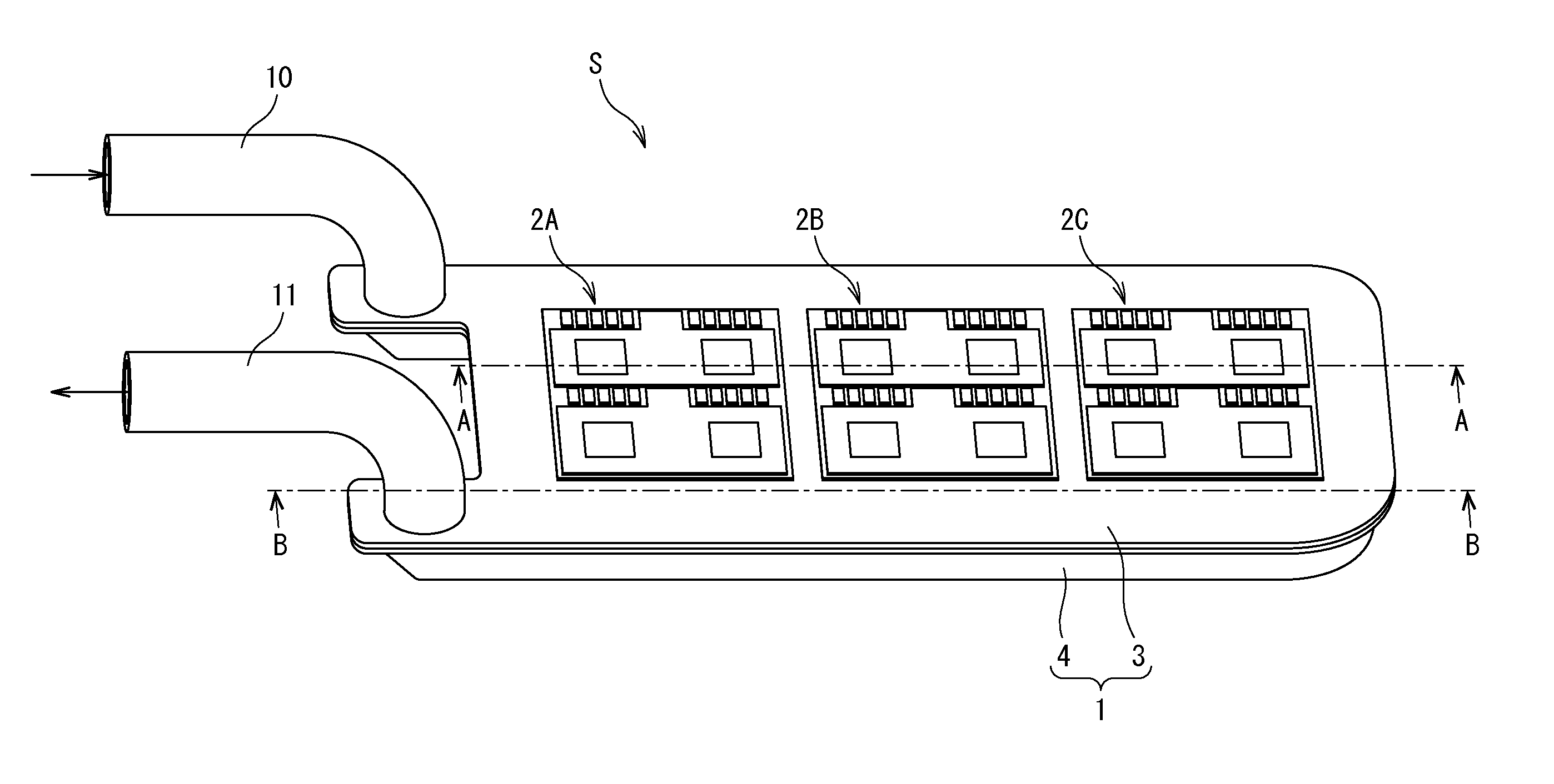
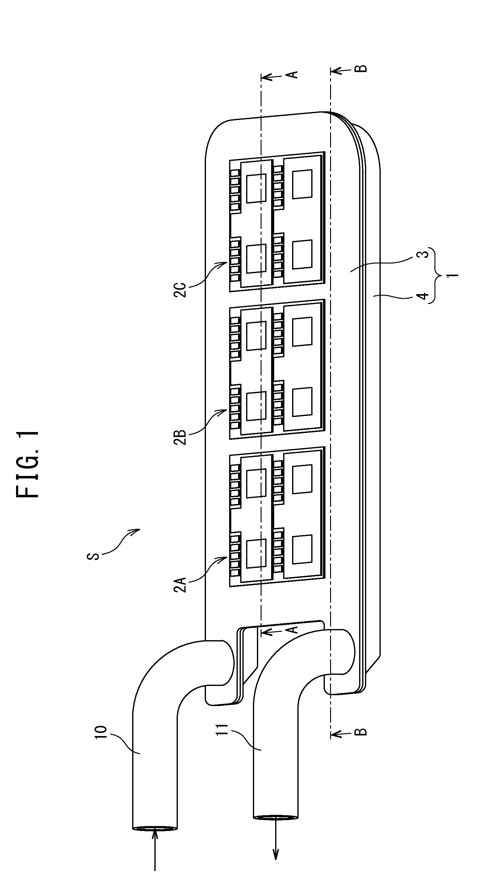
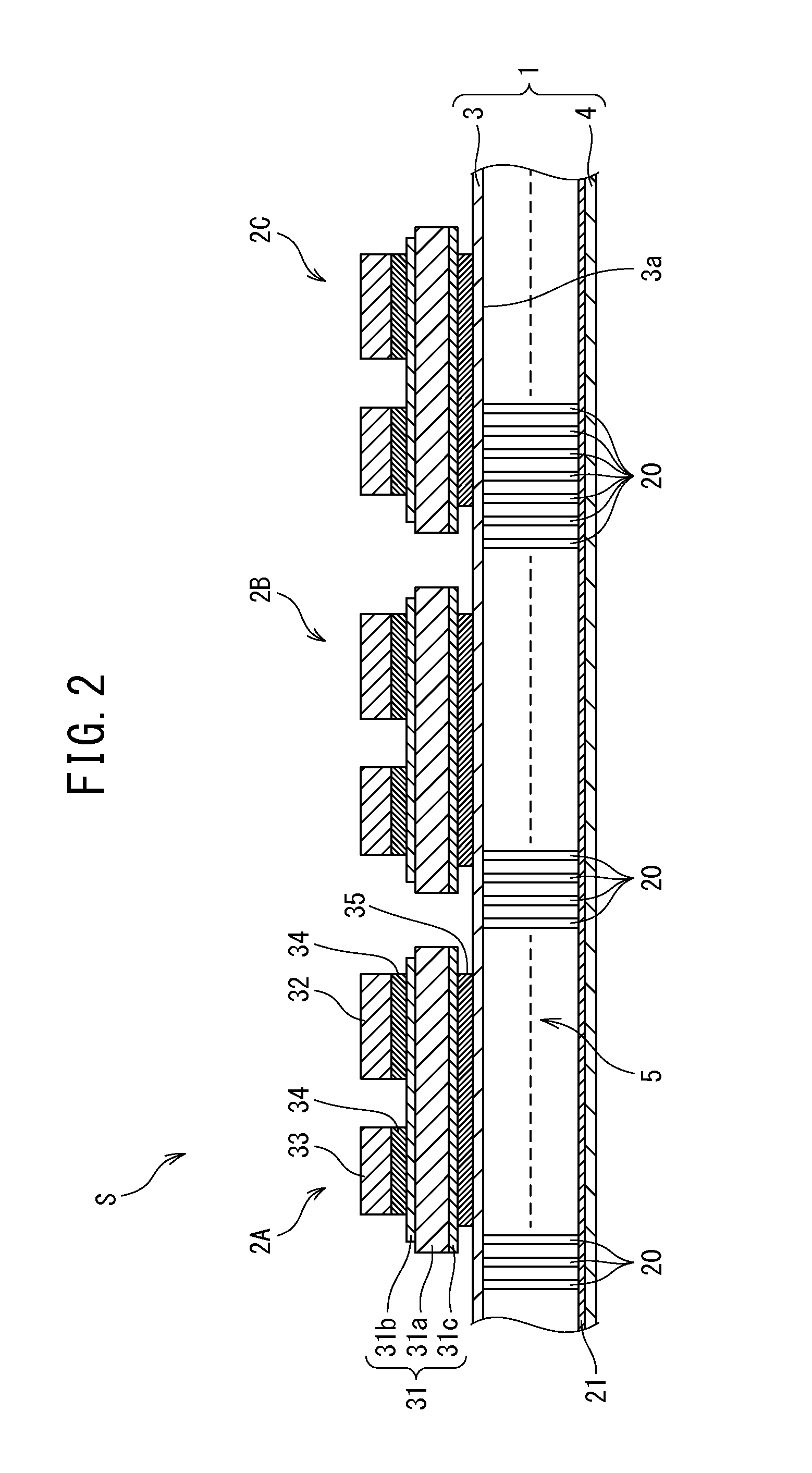
[0038]FIG. 1 is an appearance perspective view illustrating an example of a semiconductor-module according to an embodiment of the present invention, FIG. 2 is a cross-sectional view of the semiconductor-module illustrated in FIG. 1, taken along an A-A line and seen in the direction of the arrows A, FIG. 3 is a view illustrating the inside of a cooler integrated with the semiconductor-module, FIG. 4 is a cross-sectional view of the semiconductor-module illustrated in FIG. 1, taken along a B-B line and seen in the direction of the arrows B, FIG. 5 is an exploded perspective view of members implementing the semiconductor-module and FIG. 6 is a schematic configuration diagram of an electrically-driven vehicle according to the embodiment of the present invention.

[0039]As illustrated in FIGS. 1 and 2, a semiconductor-module S includes a cooler 1 and circuit-e...


PUM

PropertyMeasurementUnit
flow rateaaaaaaaaaa
height t1aaaaaaaaaa
height t2aaaaaaaaaa

Abstract

A cooler for a semiconductor-module includes: a heat sink which has an appearance of a cuboid structure to one side of which a flow rate control plate is fixed; a thermal radiation plate on an outer surface of which semiconductor devices are bonded; and a tray-shaped cooling jacket having: a coolant introduction channel; a coolant extraction channel extending in parallel to the coolant introduction channel; and a cooling channel provided between the coolant introduction and extraction channels. The heat sink is provided in the cooling channel of the cooling jacket so that the flow rate control plate extends in a boundary between the coolant extraction channel and the cooling channel, and channels provided for the heat sink extend orthogonally to the coolant introduction and extraction channels. The thermal radiation plate is fixed so as to close an opening the cooling jacket.

Description

CROSS-REFERENCE TO RELATED APPLICATIONS[0001]This application is a U.S. National Stage Application, which claims the benefit under 35 U.S.C. §371 of PCT International Patent Application No. PCT / JP2014 / 005756, filed Nov. 17, 2014, which claims the foreign priority benefit under 35 U.S.C. §119 of Japanese Patent Application No. 2013-246372, filed Nov. 28, 2013, the contents of which are incorporated herein by reference.TECHNICAL FIELD[0002]The present invention relates to a method for manufacturing a semiconductor-module cooler which cools semiconductor devices, a semiconductor-module cooler, a semiconductor-module cooling semiconductor devices arranged on the outer surface of the cooler, and an electrically-driven vehicle.BACKGROUND ART[0003]In power converters adapted for hybrid vehicles, electric vehicles, and the like, semiconductor-modules are widely used. Such semiconductor-modules, which implement controllers for energy saving, are provided with power semiconductor devices conf...

Claims


Application Information

Patent Timeline
Patent Type & Authority Applications(United States)
IPC IPC(8): B60L11/00B60K1/00H05K7/20H01L23/473B23P15/26
CPCB60L11/002H01L23/473H05K7/20927H05K7/205B60K1/00B23P15/26H01L25/18H01L2224/32225H01L2924/13055H01L24/29H01L24/32H01L24/48H01L24/73H01L25/072H01L2224/291H01L2224/48227H01L2224/73265H01L23/3735B60K2001/003B60Y2400/61H01L2924/00014B60L3/0084B60L15/007Y02T10/64H01L2924/00H01L2924/014H01L2924/00012H01L2224/45099H01L2224/45015H01L2924/207B60L50/10
Inventor GOHARA, HIROMICHIARAI, NOBUHIDE
Owner FUJI ELECTRIC CO LTD
Why Eureka
Try Eureka