Electrical control unit

a technology of electric control unit and control panel, which is applied in the direction of printed circuit aspects, transportation and packaging, and support structure mounting, etc., can solve the problems of increasing the physical size of the terminal, the inability of the structure of fig. 5 to meet the increase of the terminal, and the increase of the cost of the electronic control unit. achieve the effect of improving thermal radiative performance, high vibration resistance and quakeproof performan

Inactive Publication Date: 2005-04-05
DENSO CORP
View PDF21 Cites 31 Cited by
  • Summary
  • Abstract
  • Description
  • Claims
  • Application Information

AI Technical Summary

Benefits of technology

Accordingly, even when the non-onboard type electronic component, which is the large-size electronic component, is disposed in the case, the non-onboard type electronic component is held with the resinous frame, thereby ensuring to have the high vibration resistance. In addition, since the thermally conductive metallic case function

Problems solved by technology

Recently, the number of the input and output terminals of the electronic control units is increased significantly (for example, 50 pins to 150 pins), and thus the structure of FIG. 5 cannot meet the increase of the terminals physically.
If the shape of the connector is changed as necessary, variations of the case are increa

Method used


Image

  • Electrical control unit
  • Electrical control unit
  • Electrical control unit

Examples


Embodiment Construction

The preferred embodiments of the present invention will be explained with reference to the accompanying drawings. In the drawing, the same numerals are used for the same components and devices.

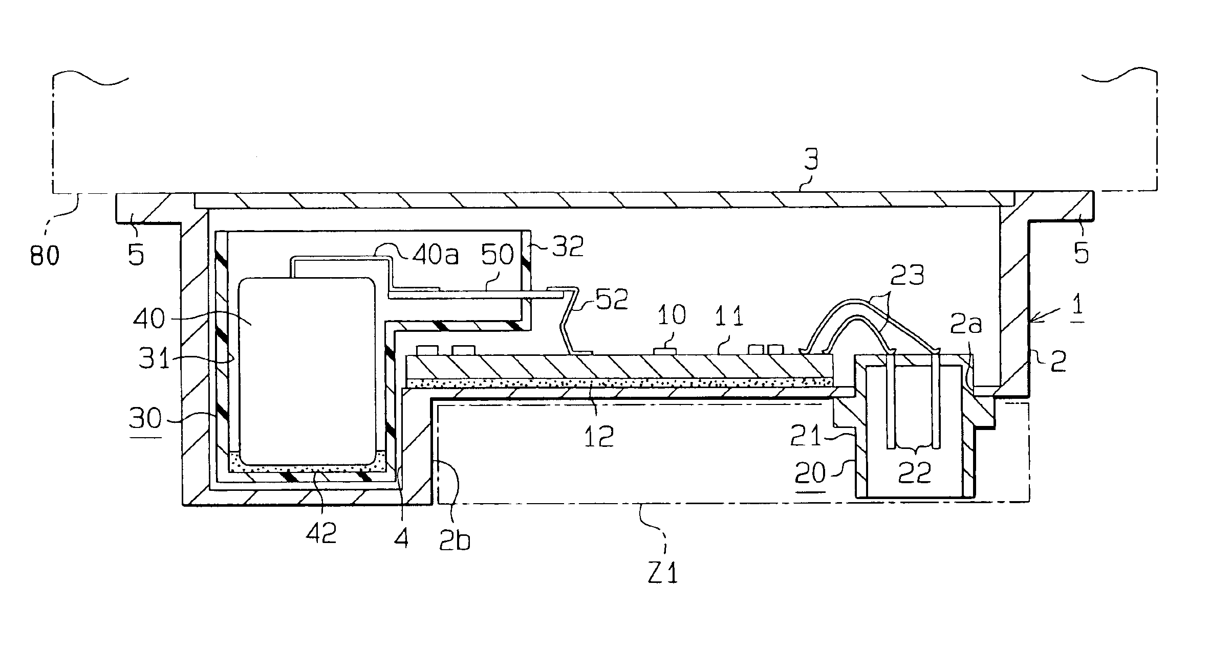
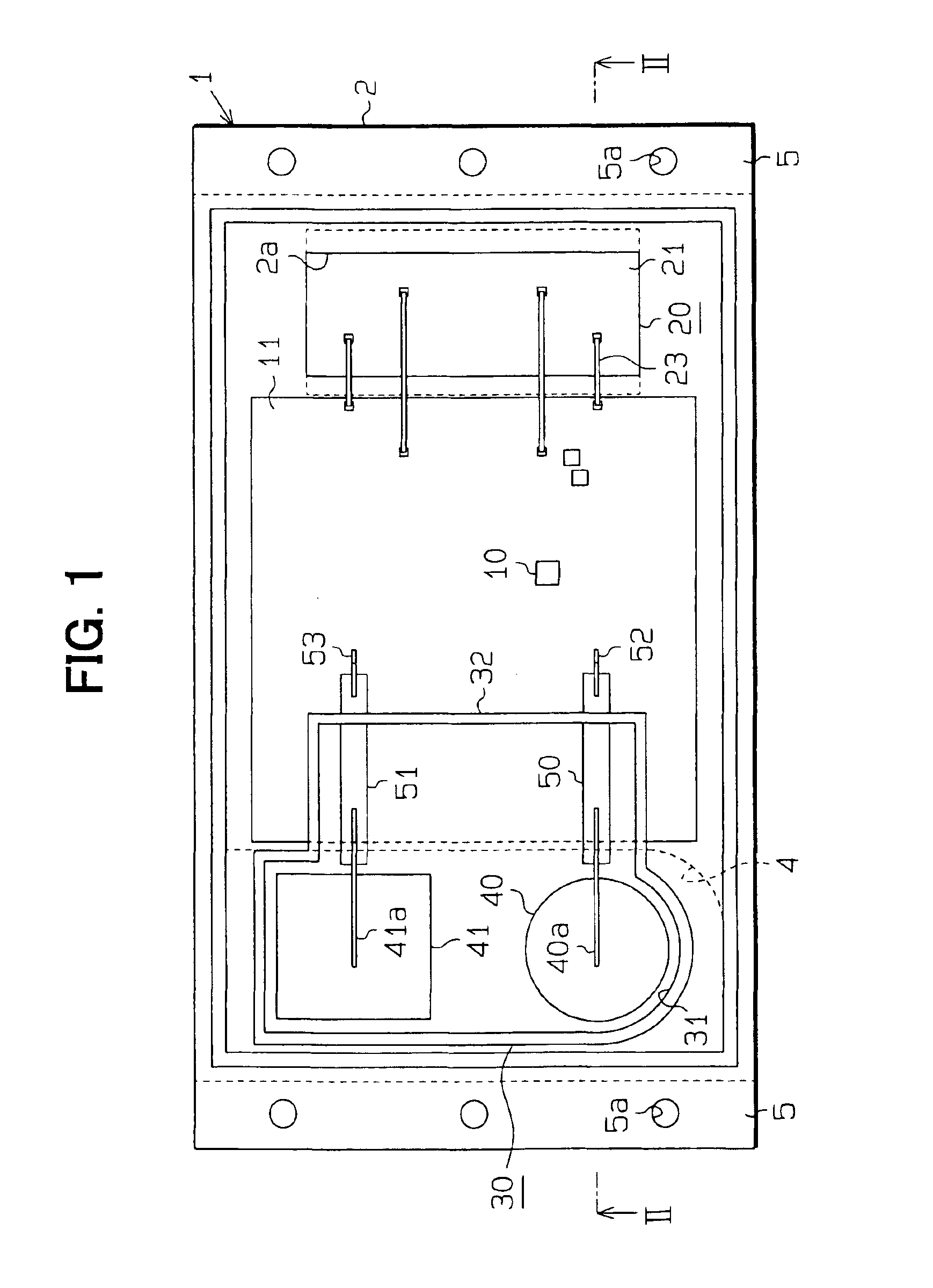
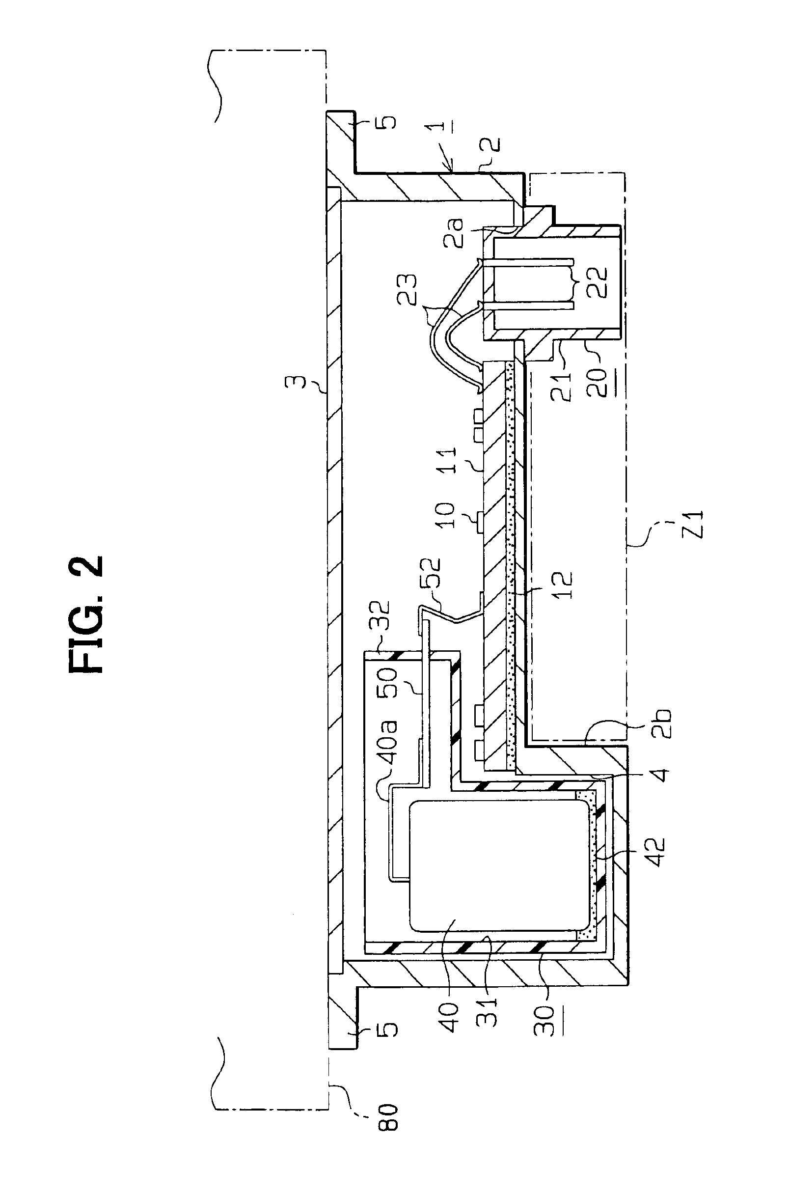
An electrical control unit (ECU) 1 shown in FIGS. 1 and 2 is used for the vehicle. It is located in an engine compartment, and it is installed directly on the engine. The unit 1 has a case 2 made of aluminum. The aluminum case 2 is a box-style that has an opening in a top surface, and it has a bottom plate and a sidewall. The opening in the top surface of the aluminum case 2 is covered with the cover 3.

A circuit board 11, which has onboard type electronic components 10, is located at a middle portion of a bottom surface of the aluminum case 2, and fixed by an adhesive 12. A connector 20 is installed at a right side position of the installation location of the circuit board 11 in the bottom surface of the aluminum case 2. That is, the aluminum case 2 is separate from the connector 20. The conne...


PUM


Abstract

An electronic control unit (ECU) includes onboard type electronic components and non-onboard type electronic components inside an aluminum case. The ECU has a circuit board for mounting the onboard type electronic component in a first portion of a bottom surface, and a concavity for installing the non-onboard type electronic components in a second portion of the bottom surface. A resinous frame is provided in the concavity to house and hold the non-onboard type electronic components.

Description

CROSS REFERENCE TO RELATED APPLICATIONSThis application is based on Japanese Patent Application No. 2002-233719 filed on Aug. 9, 2002, the contents of which are incorporated herein by reference.BACKGROUND OF THE INVENTION1. Field of the InventionThe present invention relates to an electrical control unit.2. Description of Related ArtElectrical control units such as shown in FIG. 5 and FIG. 6 are mass-produced for vehicles. In the unit shown in FIG. 5, a substrate 102 that mounts electronic components 101 is fixed by bonding on a plane plate 100 manufactured by aluminum. Large-size electronic components 104 (such as coils and capacitors), which cannot be mounted on the substrate 102, are held and fixed on a resinous frame 103 that combines a case and a connector. Bus bar (metallic electrical conductor) 105 is inserted into the resinous frame 103. The large-size electronic components 104 are electrically connected to a connective land of the substrate 102 via a lead wire 106, the bus ...

Claims


Application Information

Patent Timeline
IPC IPC(8): B60R16/02H05K3/30H05K7/14B60R16/023
CPCB60R16/0239H05K3/301H05K2201/10962H05K2201/10446
Inventor KAWABATA, AKIRATANAKA, YASUMITSUFUKAYA, YUICHIRO
Owner DENSO CORP
Why Eureka
Try Eureka