Rotator with bearing, and method for manufacturing the same

a technology of rotating shafts and bearings, which is applied in the direction of bearing cooling, gearing, hoisting equipment, etc., can solve the problems of difficult to reduce the number of working steps of the pulley and the number of components, and achieve the effect of easy integration

Inactive Publication Date: 2005-03-01
DENSO CORP
View PDF11 Cites 31 Cited by
  • Summary
  • Abstract
  • Description
  • Claims
  • Application Information

AI Technical Summary

Benefits of technology

In view of the above problem, it is an object of the present invention to reduce production cost of a rotator such as a pulley.
It is an another object of the present invention to provide a rotator that is manufactured in low cost, while a bonding strength between a rotating member and a bearing is increased.
According to the present invention, a rotator includes a rotating member made of resin, and a bearing attached to a radial inner side of the rotating member. The bearing includes an outer ring integrated to the rotating member by an insert molding, an inner ring positioned at a radial inside of the outer ring, and a bearing ball that is disposed to rolling-contact an inner peripheral surface of the outer ring and an outer peripheral surface of the inner ring. In the rotator, the outer ring has an axial dimension larger than an axial dimension of the inner ring in an axial direction of the rotating member. Because the bearing and the rotating member are integrated to each other through the insert molding, a metal insert member is not required to be disposed between the rotating member and the bearing, thereby reducing production cost of the rotator. In addition, because the outer ring has the axial dimension larger than the axial dimension of the inner ring, a bonding area between the bearing and the rotating member can be increased, and a connection strength therebetween can be increased while an outer surface of the bearing can be increased. Accordingly, heat radiation performance of the bearing can be improved.
Preferably, the outer ring has an outer peripheral surface contacting the rotating member, and the outer peripheral surface has an uneven portion. Therefore, the outer ring of the bearing can be engaged with the rotating member in the insert molding, and the connection strength between the bearing and the rotating member can be effectively increased.
Preferably, the rotating member includes two projections protruding to a radial inside of the outer peripheral surface of the outer ring, and the two projections contact two axial ends of the outer ring to pinch the outer ring from the two axial ends. Therefore, the bearing is fixed by the projections of the rotating member in the axial direction, and connection strength between the bearing and the rotating member can be further improved. On the other hand, the outer ring has the outer peripheral surface, two axial ends and two chamfer surfaces connecting the outer peripheral surface and the axial ends. In this case, the rotating member contacts the outer peripheral surface and the chamfer surfaces of the outer ring.
The rotator of the present invention is manufactured by the insert molding. In the inserting molding, at least the outer ring of the bearing is arranged in a die at a predetermined position, and a resin is injected in the die to form the rotating member integrated to the outer ring, at a radial outside of the outer ring. When only the outer ring of the bearing is provided in the die in the insert molding, the bearing ball is attached to the outer ring so that the bearing ball rolling-contacts the inner peripheral surface of the outer ring, and the inner ring is attached to the bearing ball at a radial inside of the outer ring so that the bearing ball rolling-contacts the inner ring. Alternatively, all the bearing including the outer and inner rings and the bearing ball can be arranged in the die in the insert molding. Accordingly, the bearing and the rotating member can be readily integrated.

Problems solved by technology

However, since a bearing is press-fitted to an inner peripheral surface of the metal member, the inner peripheral surface requires finishing operation such as cutting.
Therefore, it is difficult to reduce the number of working steps of the pulley and the number of components thereof.

Method used


Image

  • Rotator with bearing, and method for manufacturing the same
  • Rotator with bearing, and method for manufacturing the same
  • Rotator with bearing, and method for manufacturing the same

Examples


first embodiment

(First Embodiment)

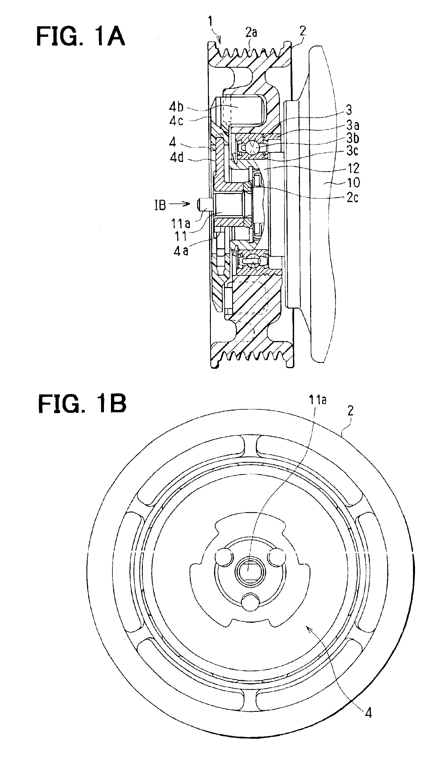
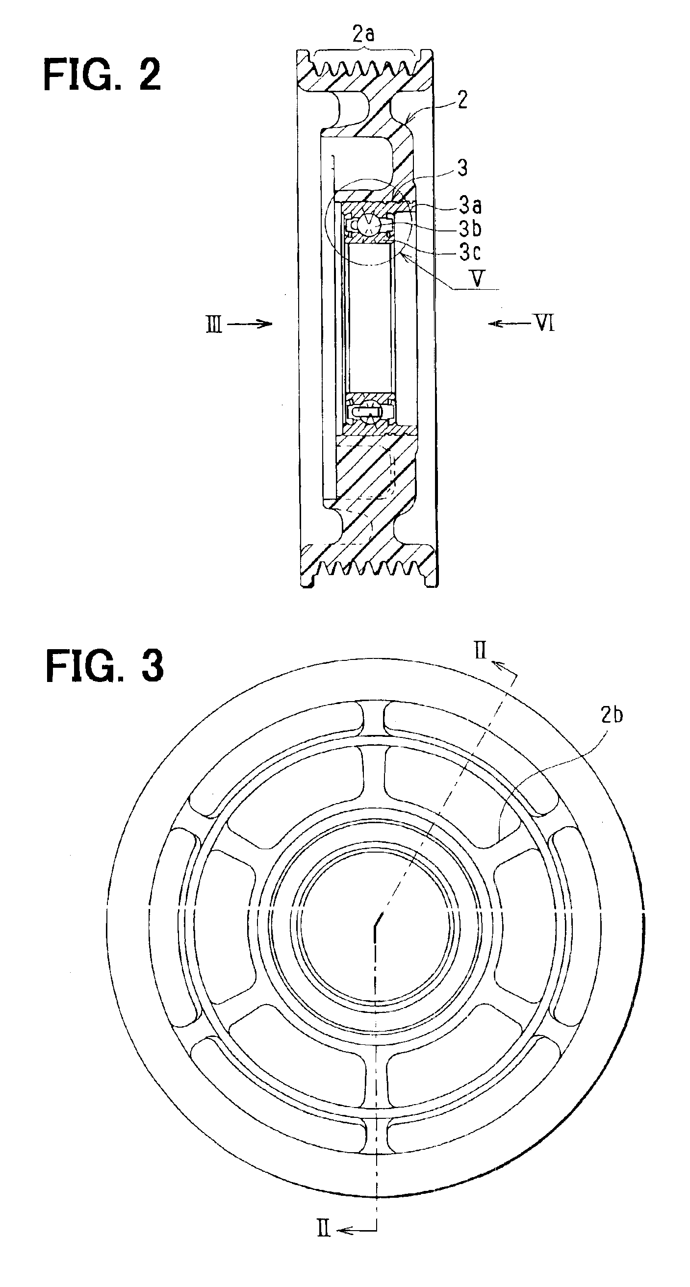
In the first embodiment, a rotator of the present invention is typically used for a pulley for transmitting motive power of a vehicle engine to a compressor. As shown in FIGS. 1A, 1B and 2, a pulley 1 includes a pulley main body 2 that is a rotating member made of resin, and a radial rolling bearing 3. Plural rows of V-grooves 2a are formed on an outer peripheral portion of the pulley main body 2, and a pulley drive belt is provided on the plural rows of V-grooves 2a. The radial rolling bearing 3 is attached to a radial inner side of the pulley main body 2. FIG. 3 is a side view when being viewed from the arrow III in FIG. 2, and FIG. 4 is a side view when being viewed from the arrow VI in FIG. 2. Further, FIG. 2 is a cross-sectional view taken along the line II—II in FIG. 3.

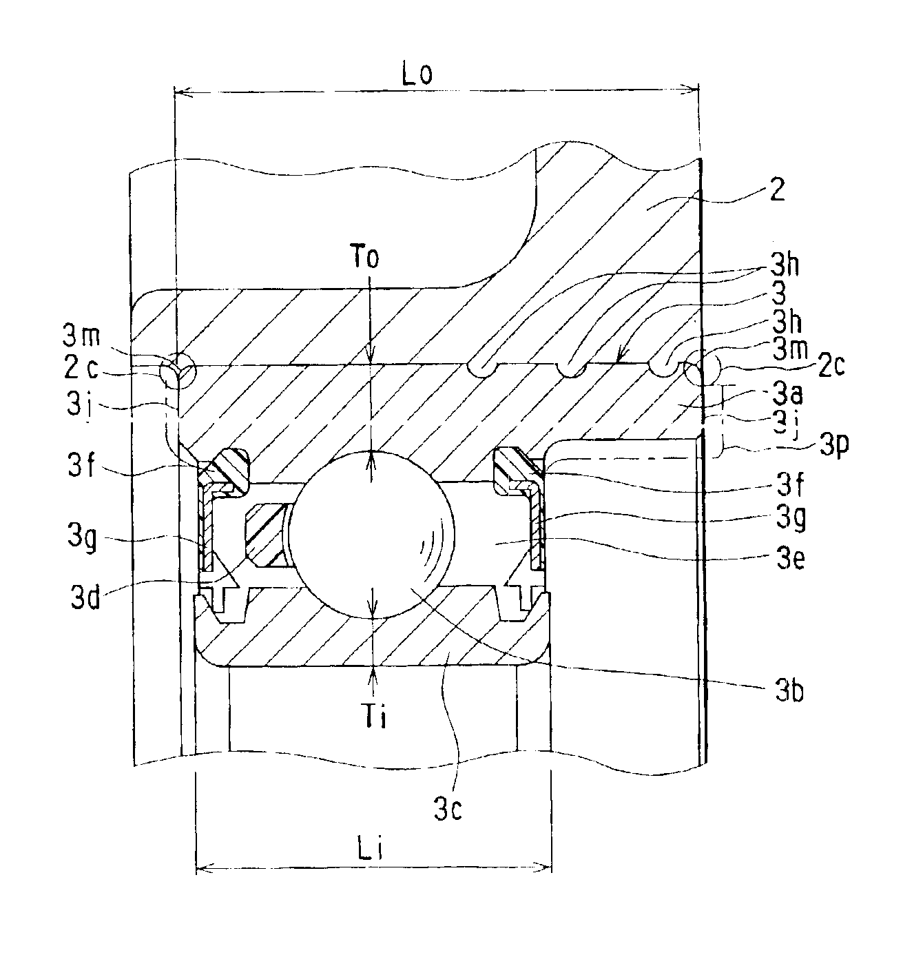
As shown in FIG. 5, the radial rolling bearing 3 includes an outer ring 3a integrated to the pulley main body 2, bearing balls 3b, an inner ring 3c disposed radial inside of the outer ring 3a, ...

second embodiment

(Second Embodiment)

In the second embodiment, as shown in FIGS. 8A, 8B, an outer radial dimension D1 of the outer ring 3a is defined at the position where the bearing balls 3b are disposed, and an outer radial dimension D2 of the outer ring 3a is defined at the other positions. The outer radial dimension D1 is made larger than the outer radial dimension D2, to form steps on the outer ring 3a as shown in FIGS. 8A and 8B. Therefore, the mechanical strength of the outer ring 3a can be increased, so that the bearing-ball track surface of the outer ring 3a can be prevented from being deformed due to molding pressure in the insert molding. Further, an amount of heat capable of being transmitted to the heat radiation portion 3p can be increased, thereby further improving heat radiation performance of the radial rolling bearing 3. In the second embodiment, the other parts are similar to those of the above-described first embodiment, and detail explanation thereof is omitted.

third embodiment

(Third Embodiment)

In the third embodiment, as shown in FIG. 9, a spiral recess portion 3q is provided on an inner peripheral surface of the heat radiation portion 3p for facilitating the heat radiation. Therefore, the heat radiation area of the heat radiation portion 3p, that is, the surface area thereof is increased. Here, the recess portion 3q can be provided in another shape such as a plural-concentric shape and a crossing-spiral shape, without being limited to the spiral shape. According to the third embodiment, by providing the recess portion 3q in the heat radiation portion 3p, the heat radiation can be effectively facilitated.

In the third embodiment, the other parts are similar to those of the above-described first embodiment, and detail explanation thereof is omitted.


PUM

PropertyMeasurementUnit
axial dimensionaaaaaaaaaa
thicknessaaaaaaaaaa
flat shapeaaaaaaaaaa

Abstract

A pulley includes a radial rolling bearing and a pulley main body which are integrated to each other by an insert molding method. Therefore, a metal insert member is not required between the resin pulley main body and the radial rolling bearing, thereby reducing production cost of the pulley. Further, an axial dimension of an outer ring of the radial rolling bearing is set larger than an axial dimension of an inner ring thereof, so that a contact area between the radial rolling bearing and the pulley main body is increased. Therefore, a connection strength between the radial rolling bearing and the pulley main body is increased, and a surface area of the radial rolling bearing is increased, thereby improving heat radiation performance of the radial rolling bearing.

Description

CROSS-REFERENCE TO RELATED APPLICATIONThis application is related to and claims priority from Japanese Patent Application No. 2002-5839 filed on Jan. 15, 2002, the content of which is hereby incorporated by reference.BACKGROUND OF THE INVENTION1. Field of the InventionThe present invention relates to a rotator including a bearing, which is suitably used for a pulley for transmitting power. Further, the present invention relates to a method for manufacturing the rotator.2. Description of Related ArtIn a conventional pulley for transmitting motive power disclosed in JP-A-2001-227620, a generally cylindrical metal member is integrated with a resinous pulley main body by using an insert molding method. However, since a bearing is press-fitted to an inner peripheral surface of the metal member, the inner peripheral surface requires finishing operation such as cutting. Therefore, it is difficult to reduce the number of working steps of the pulley and the number of components thereof.SUMMA...

Claims


Application Information

Patent Timeline
Patent Type & Authority Patents(United States)
IPC IPC(8): B29C45/14F16C35/04F16C37/00F16H55/49F16C35/067F16H55/36B29K105/22B29L31/32F16C19/06F16C33/64
CPCB29C45/1459F16C37/007F16H55/49F16C35/067B29C45/14311B29L2031/04Y10T29/49682F16C13/006F16C19/06F16C33/586F16C2361/63
Inventor TABUCHI, YASUOKISHIBUCHI, AKIRA
Owner DENSO CORP
Why Eureka
Try Eureka