

Rotor for modulated pole machine
- Summary
- Abstract
- Description
- Claims
- Application Information
AI Technical Summary
Benefits of technology
Problems solved by technology
Method used
Image

Examples
Embodiment Construction
[0051]In the following description, reference is made to the accompanying figures, which show by way of illustration how the invention may be practiced.
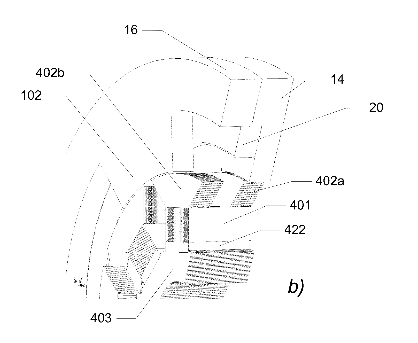
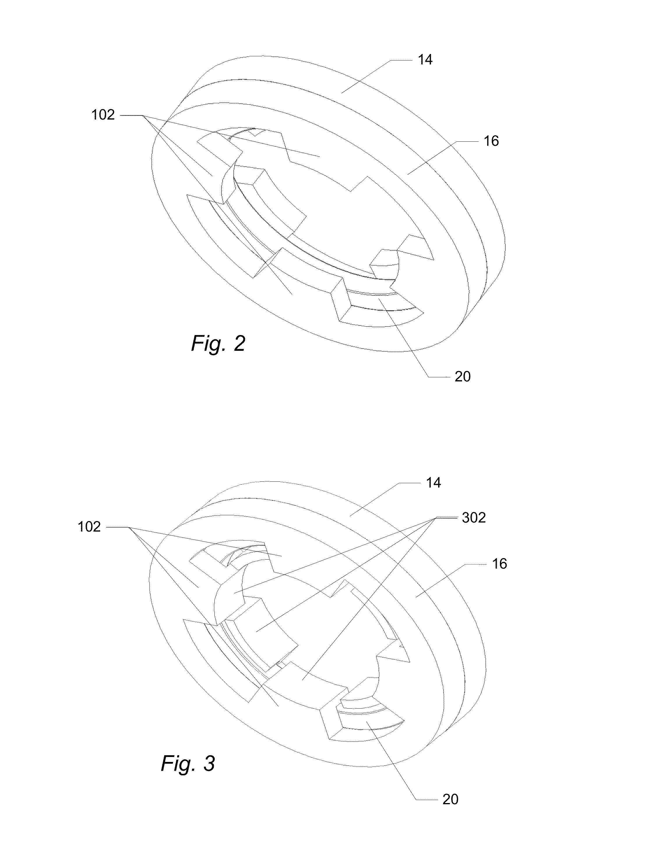
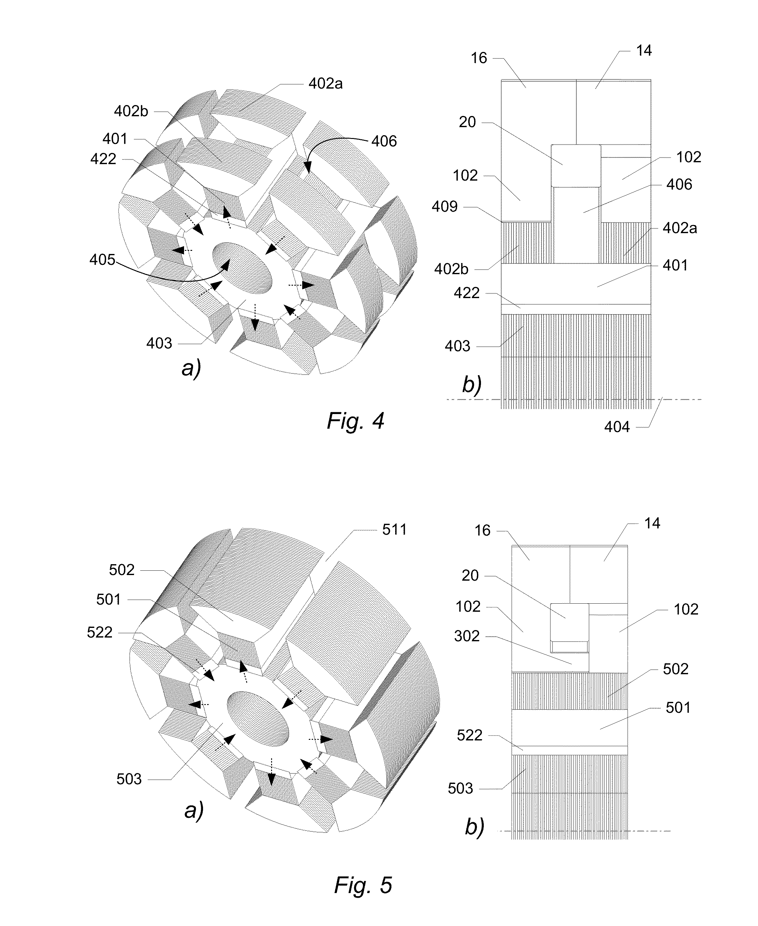
[0052]This invention is in the field of a modulated pole electric machine 100 of which one example is shown in FIG. 1a in a schematic, exploded, perspective view. The modulated pole electric machine stator 10 is basically characterised by the use of a central single coil 20 that will magnetically feed multiple teeth 102 formed by the soft magnetic core structure. The stator core is then formed around the coil 20 while for other common electrical machine structures the coil is formed around the individual tooth core section. Examples of the modulated pole machine topology are sometimes recognised as e.g. Claw-pole-, Crow-feet-, Lundell- or TFM-machines. More particularly the shown modulated pole electric machine 100 comprises two stator core sections 14, 16 each including a plurality of teeth 102 and being substantially circular, a co...
PUM
 Abstract
Description
Claims
Application Information