Low-cost low-cog PM machine

a generator and low-cost technology, applied in the direction of rotating magnets, synchronous machines with stationary armatures, magnetic circuit rotating parts, etc., can solve the problem of low-cost pm machine design with low cogging torque, and achieve the effect of reducing stator core manufacturing costs, reducing cogging torque, and enabling cost efficiency

Active Publication Date: 2016-07-12
MCINTOSH DEVON R
View PDF11 Cites 0 Cited by
  • Summary
  • Abstract
  • Description
  • Claims
  • Application Information

AI Technical Summary

Benefits of technology

[0013]The invention utilizes stator modularity to enable cost efficiency by significantly decreasing stator core manufacturing costs, and coil forming and fixturing costs in several ways. Minimizing costs extend to a novel, lightweight, support structure that does not require the usual encasement structure. The approach presents a challenge to mitigating cogging torque via popular methods; therefore a novel anti-cogging approach was developed that is a natural outgrowth of the modular layout instead of being negatively impacted by. The result is a low cost PM machine design with low cogging torque.

Problems solved by technology

The approach presents a challenge to mitigating cogging torque via popular methods; therefore a novel anti-cogging approach was developed that is a natural outgrowth of the modular layout instead of being negatively impacted by.
The result is a low cost PM machine design with low cogging torque.

Method used


Image

  • Low-cost low-cog PM machine
  • Low-cost low-cog PM machine
  • Low-cost low-cog PM machine

Examples


Embodiment Construction

[0031]The present invention will now be described more fully hereinafter with reference to the accompanying Drawings, in which preferred embodiments of the invention are shown. It is, of course, understood that this invention may, however, be embodied in many different forms and should not be construed as limited to the embodiments set forth herein; rather, these embodiments are provided so that the disclosure will be thorough and complete, and will fully convey the scope of the invention to those skilled in the art. It is, therefore, to be understood that other embodiments can be utilized and structural changes can be made without departing from the scope of the present invention.

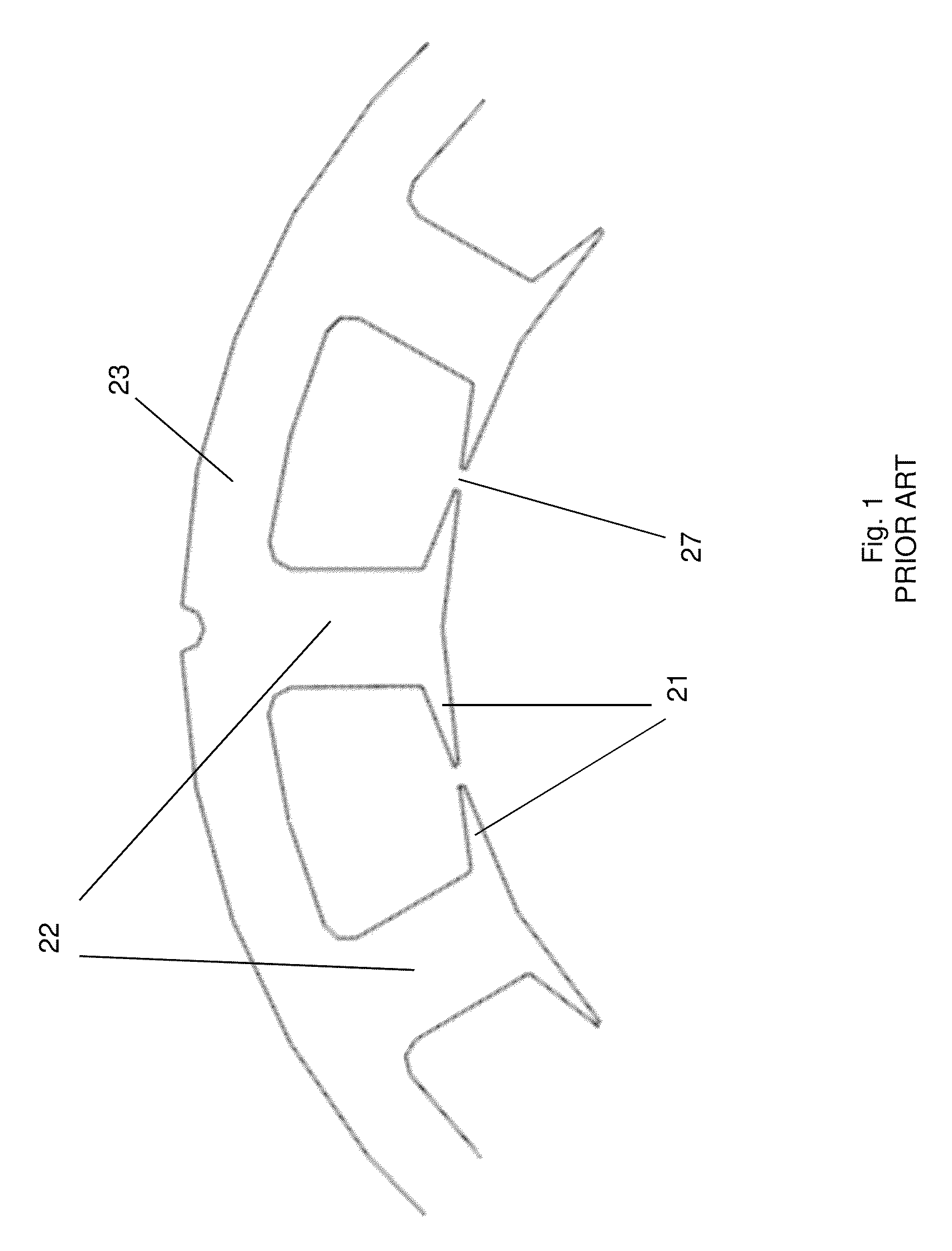
[0032]FIG. 1 is a prior art stator design showing the semi-closed slots 27. The teeth 22 are connected via the stator back-iron 23, which together with the stator shoes 21 form the stator (coils not shown). The rotor with rotor magnets are not shown here (see the following figures), but when ratios between...


PUM


Abstract

Due largely to their high torque-to-current and torque-to-volume ratios, permanent magnet (PM) motors and generators are increasingly being used in a wide range of high performance applications, such as industrial drives, robotics, computer peripherals, and automotive applications. The present invention utilizes stator modularity to enable cost efficiency by significantly decreasing stator core manufacturing costs, and coil forming and fixturing costs in several ways. Minimizing costs extend to a novel, lightweight, support structure that does not require the usual encasement structure. The approach presents a challenge to mitigating cogging torque via popular methods; therefore a novel anti-cogging approach was developed that is a natural outgrowth of the modular layout instead of being negatively impacted by. The result is a low cost PM machine design and method with low cogging torque.

Description

SUPPORT FOR THE INVENTION[0001]The invention described herein was supported by Small Business Innovation Research (SBIR) pursuant to Competitive Grant no. 2011-33610-30858 from the USDA National Institute of Food and Agriculture.BACKGROUND OF THE INVENTION[0002]1. Field of the Invention[0003]The invention relates generally to permanent magnet motors and generators, and particularly to minimizing the cost and cogging torque of such PM machines.[0004]2. Description of Related Art[0005]Due largely to their high torque-to-current and torque-to-volume ratios, permanent magnet (PM) motors and generators are increasingly being used in a wide range of high performance applications such as industrial drives, robotics, computer peripherals, and automotive applications. The PM's are mounted on the rotor, which is the rotating part of the machine, while the stator, which is the stationary part of the machine, contains the coils wrapped around stator teeth that are interconnected via the stator ...

Claims


Application Information

Patent Timeline
Patent Type & Authority Patents(United States)
IPC IPC(8): H02K1/14H02K29/03H02K1/18
CPCH02K1/148H02K1/185H02K29/03
Inventor MCINTOSH, DEVON R.
Owner MCINTOSH DEVON R
Why Eureka
Try Eureka