Sensor system, method for operating sensor system

A sensor, temperature sensor technology, applied in the field of sensor systems

Pending Publication Date: 2022-02-22
ROBERT BOSCH GMBH
View PDF5 Cites 0 Cited by
  • Summary
  • Abstract
  • Description
  • Claims
  • Application Information

AI Technical Summary

Problems solved by technology

However, TGO effects can also appear in lateral acceleration sensors (or x / y sensors), i.e. sensors with a detection direction parallel to the substrate surface of the MEMS chip

Method used


Image

  • Sensor system, method for operating sensor system
  • Sensor system, method for operating sensor system
  • Sensor system, method for operating sensor system

Examples


Embodiment Construction

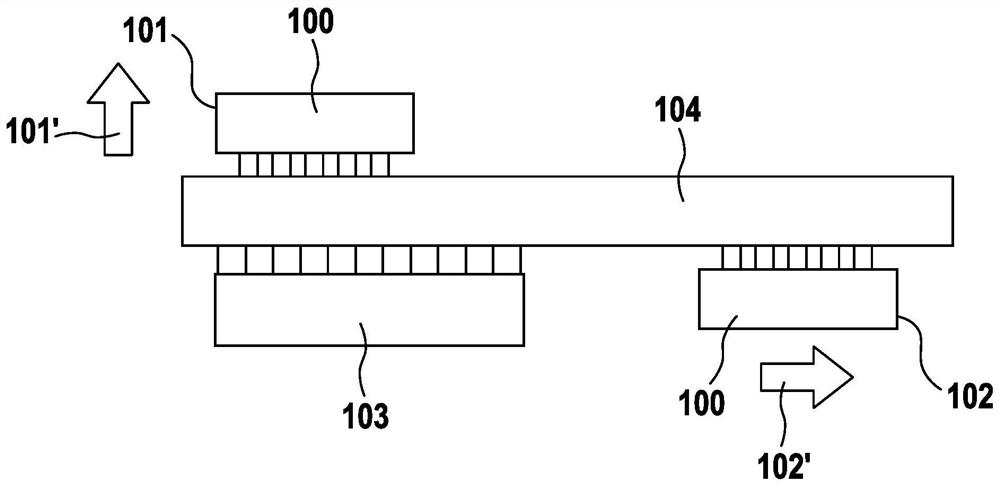
[0053] exist figure 1 A schematic diagram of a heat source 103 that can induce a temperature gradient in a sensor or chip arrangement 100 is shown in . The chip arrangement 100 is located near a heat source 103, for example an application processor 103 on a printed circuit board 104 (printed circuit board, PCB) of a smartphone. Depending on the relative position of the chip arrangement 100 with respect to the heat source 103 , a vertical or lateral temperature gradient or a combination thereof is formed in the sensor module. For example, for figure 1 In the case of arranging the chip arrangement 100 at the first position 101, a vertical temperature gradient occurs within the MEMS chip 100, indicated by the box arrow 101'. For the basis figure 1 In the case of arranging the chip arrangement 100 at the second position 102, a lateral temperature gradient occurs within the MEMS chip 100, indicated by the box arrow 102'. Here, chip arrangement 100 refers to one or more integrat...


PUM


Abstract

A sensor system is claimed. A sensor system including a chip arrangement, the chip arrangement including a sensor and an acceleration sensor, and the sensor system including a processor circuit. The processor circuit is configured in such a way that: one or multiple temperature-dependent variables and / or properties of the sensor are ascertained, and an offset of a signal of the acceleration sensor induced by a temperature gradient is corrected with the aid of the one or the multiple ascertained temperature-dependent variables and / or properties of the sensor.

Description

technical field [0001] The invention proceeds from a sensor system comprising a chip arrangement, wherein the chip arrangement has a sensor and an acceleration sensor, wherein the sensor system has a processor circuit. Background technique [0002] Microelectromechanical systems (MEMS), such as inertial sensors, for example for measuring acceleration and / or rotational speed, are produced in large numbers for different applications. As such, such sensors are also used in numerous applications in the automotive and consumer fields. "Balance bars" are often used for capacitive acceleration sensors with a detection direction (z-direction) perpendicular to the wafer plane. The sensor principle of these balance bars is based on a spring-mass system in which, in the simplest case, a movable seismic mass (seismische Masse) with two counter electrodes fixed to the substrate forms two flat plates capacitor. The seismic mass is connected to the base by one or more torsion springs. ...

Claims


Application Information

Patent Timeline
Patent Type & Authority Applications(China)
IPC IPC(8): G01P3/38
CPCG01P3/38G01P1/006G01P15/0802G01P2015/0831G01P21/00G01P1/023B81B7/0087H01L23/34
Inventor W·盖格尔I·卡达尔-内梅特J·克拉森
Owner ROBERT BOSCH GMBH
Why Eureka
Try Eureka