Novel sliding fork spline broaching tool

A technology of spline tooling and sliding fork, which is applied in the field of new sliding fork pull spline tooling, can solve the problems of unsuitable low work intensity, high efficiency, high work intensity of workers, cumbersome operation process, etc., so as to reduce the labor intensity of workers and improve The effect of enterprise competitiveness and ease of use

Active Publication Date: 2015-05-20
XUCHANG YUANDONG DRIVE SHAFT +1
View PDF5 Cites 0 Cited by
  • Summary
  • Abstract
  • Description
  • Claims
  • Application Information

AI Technical Summary

Problems solved by technology

The operation process of this fixture is relatively cumbersome, and the workers' work intensity is relatively high, and the work efficiency is low. It is seriously not suitable for the current low-work intensity and high-efficiency working methods.

Method used


Image

  • Novel sliding fork spline broaching tool
  • Novel sliding fork spline broaching tool
  • Novel sliding fork spline broaching tool

Examples


Embodiment Construction

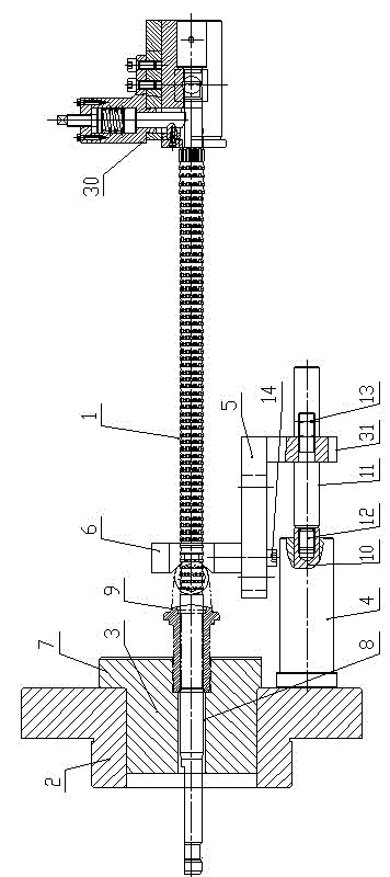
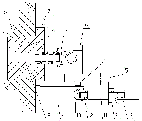
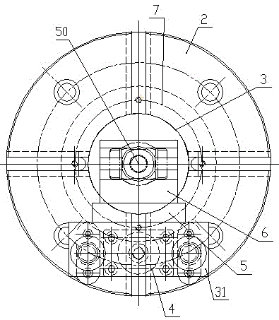
[0024] Such as Figure 1 ~ Figure 4 As shown, a novel sliding fork pulling spline tooling of the present invention includes a sliding fork positioning fixture and a broach positioning fixture 30 , and the front end of the broach 1 passes through the sliding fork positioning fixture and is inserted into the broach positioning fixture 30 . Both the moving fork positioning fixture and the broach positioning fixture 30 are arranged on the broaching machine.

[0025] The sliding fork positioning fixture includes a transition sleeve 2, a positioning sleeve 3, a cylinder 4, a support plate 5 and a V-shaped block 6. The positioning sleeve 3 is installed in the transition sleeve 2 from the front end of the transition sleeve 2. The front end of the positioning sleeve 3 is provided with a The front end of the positioning sleeve 3 is pressure-contacted with the limit plate 7, and the positioning sleeve 3 and the limit plate 7 are integrated. The center of the positioning sleeve 3 is provi...


PUM


Abstract

The invention relates to a novel sliding fork spline broaching tool. The novel sliding fork spline broaching tool comprises a sliding fork positioning fixture and a broach positioning fixture, wherein the front end of a broach penetrates through the sliding fork positioning fixture and is inserted in the broach positioning fixture. The novel sliding fork broaching spline tool provided by the invention is extremely convenient to use, the labor intensity of workers is reduced, the manpower cost is reduced, the working efficiency is improved, and the purposes of decreasing the cost and increasing the efficiency are achieved; the tool is relatively accurate to position, the product quality of sliding forks after being processed can be ensured better, the qualified rate of processed products is improved, and the tool has extremely positive meanings for improving the competitiveness of enterprises.

Description

technical field [0001] The invention belongs to the technical field of mechanical processing, in particular to a novel sliding fork pull spline tooling. Background technique [0002] With the rapid development of my country's automobile industry, the auto parts manufacturing industry has been brought into the fast lane of rapid development. With the increasing maturity of its processing and manufacturing technology and the advancement of mechanical equipment technology, coupled with the application of a large number of numerical control equipment and the progress of specialized mass production, the competition in the field of auto parts processing has become more and more fierce, and it has entered the era of meager profits. At the same time, coupled with the increasing demand for price cuts from end customers and the cost transfer of main engine manufacturers, auto parts processing companies are forced to continue to innovate and improve, and abandon the previous production...

Claims


Application Information

Patent Timeline
Patent Type & Authority Patents(China)
IPC IPC(8): B23D41/00B23D41/06B23Q3/00B23Q3/08
Inventor 陈云升王文张志斌雷务然顾鲜美张俊华付浩峰郭要闯李磊周建喜马喜岭张鹏超尚国生韩利李建勋曹善江李红俊侯光辉王建国唐记敏齐瑞晓柴二帅姚晋业刘金檑尚向辉
Owner XUCHANG YUANDONG DRIVE SHAFT
Why Eureka
Try Eureka