Method of processing objects by focused ion beam system and carrier used therewith

a technology of focused ion beam and object, which is applied in the field of object processing techniques, can solve the problems of increasing the processing time consumption, increasing the complexity of operation, and the inability to solve the patent drawback, so as to improve the processing efficiency and reduce the risk. , the effect of simplifying the operation

Active Publication Date: 2010-07-01
IND TECH RES INST
View PDF11 Cites 0 Cited by
  • Summary
  • Abstract
  • Description
  • Claims
  • Application Information

AI Technical Summary

Benefits of technology

[0017]Compared with the prior art, the present invention spares the object processing steps from a second eucentric height adjustment required in the prior art due to a height difference between the processed object to be moved and the carrying base, thereby simplifying the operation, improving the processing efficiency, and reducing the risk.

Problems solved by technology

However, in practice, a height difference often exists between the position of an analysis carrier for carrying a sample and the position of an original specimen (object) processing area.
Such a drawback is not solved in the patent.
Therefore, the second eucentric height adjustment increases the processing time consumption, the operation complexity, and the security risk of the sample.

Method used


Image

  • Method of processing objects by focused ion beam system and carrier used therewith
  • Method of processing objects by focused ion beam system and carrier used therewith
  • Method of processing objects by focused ion beam system and carrier used therewith

Examples


first embodiment

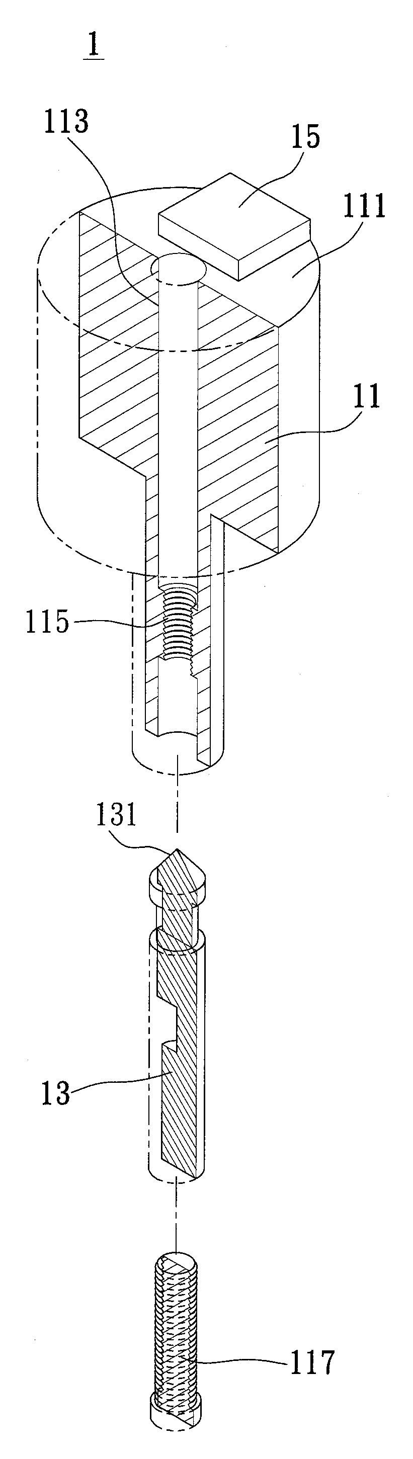
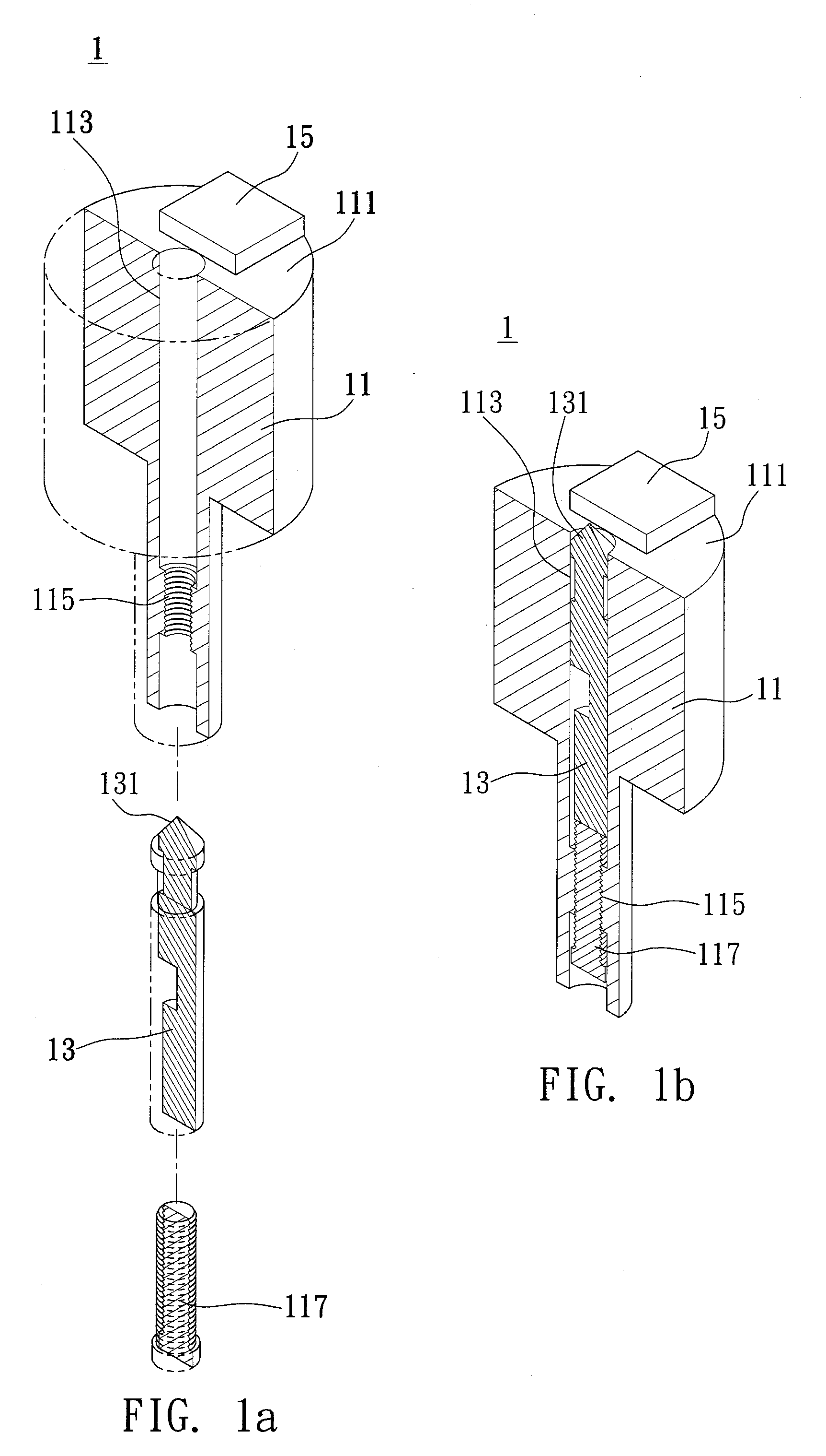
[0022]FIGS. 1a and 1b show a carrier according to a first embodiment of the present invention, wherein the carrier is used in the method of processing objects according to the present invention. In the present embodiment, the carrier is used for fabricating a three-dimensional TEM (Transmission Electron Microscope) sample; the example is however not intended to limit the present invention. Further, in order to make the characteristics and structures of the present invention more clear, only structures related to the present invention are shown in the drawings.

[0023]FIG. 1a is an exploded view of the carrier and FIG. 1b is an assembly view of the carrier.

[0024]Referring to FIGS. 1a and 1b, the method of processing objects according to the present embodiment is applicable to a FIB system with a carrier 1 as shown in FIGS. 1a and 1b. The carrier 1 comprises a carrying base 11 and a carrying member 13 integrated with the carrying base 11. After a processed object is moved to the carryin...

second embodiment

[0034]FIG. 3 is an assembly view of a carrier according to a second embodiment of the present invention. As shown in the drawing, the carrier 2 comprises a carrying base 21 and a carrying member 23 integrated with the carrying base 21. The carrying base 21 comprises: a processing portion 211 having an object 25 disposed thereon, a receiving portion 213 for receiving the carrying member 23, a positioning portion 215 connected to the receiving portion 213, and a lift mechanism 217 for lifting the carrying member 23 vertically.

[0035]Unlike the first embodiment, the top of the carrying member 23 of the present embodiment has a carrying body 27 disposed thereon. In addition, the carrying body 27 is an integrated circuit to be repaired or a micro / nanostructure to be assembled, but it is not limited thereto.

[0036]In an embodiment, the carrying body 27 is an integrated circuit to be repaired, and the object 25 is a bulk material which contains specific ingredients or an element for a specif...


PUM


Abstract

A method of processing objects by a FIB (Focused Ion Beam) system and a carrier used therewith are provided. The carrier includes a carrying member and a processing portion having an object disposed thereon. Before the carrier is disposed into the FIB system, the carrying member is set to be flush in height with the processing portion having the object disposed thereon. After an eucentric height adjustment inside the FIB system, both the carrying member and the processing portion are in a same plane with the eucentric point of the system. Therefore, after the object on the processing portion is processed, a processed object or a processed block of the object can be moved to the carrying member without performing further eucentric height adjustment with respect to the carrying member.

Description

BACKGROUND OF THE INVENTION[0001]1. Field of the Invention[0002]The present invention relates generally to object processing techniques, and more particularly to a method of processing objects by a focused ion beam system to fabricate samples and a carrier applied to the method.[0003]2. Description of Related Art[0004]A focused ion beam (FIB) system uses an electromagnetic lens to focus an ion beam to an extra small spot so as to perform processing such as cutting and shaping. Since such a technique allows precise positioning, less material limitation, and minor specimen destruction, it can be widely applied to the fields of analysis sample preparation, IC replacement and repair, and micro / nanostructure fabrication after combining with a micro-manipulation technique.[0005]For example, a method disclosed by U.S. Pat. No. 5,270,552 comprises the steps of: processing a desired portion of an object by an FIB system so as to form a sample, fixing the sample to a probe attached to a manip...

Claims


Application Information

Patent Timeline
Patent Type & Authority Applications(United States)
IPC IPC(8): G21K5/04G21K5/08
CPCH01J37/20H01J2237/20235H01J2237/20242H01J2237/31745H01J2237/31749
Inventor LO, SHEN-CHUANLAI, MING-WEILEE, SHI-RILIN, LI-JIAUN
Owner IND TECH RES INST
Why Eureka
Try Eureka