Single-phase brushless motor

a brushless motor and single-phase technology, applied in the direction of dynamo-electric machines, electrical equipment, magnetic circuit shapes/forms/construction, etc., can solve the problems of increased cogging torque, vibration or noise in the rotation of the motor, and the need for superior start-up stability and low cogging torque, so as to reduce the driving current required to obtain the same running torque, the effect of carefully handling

Active Publication Date: 2013-11-14
MINEBEAMITSUMI INC
View PDF5 Cites 10 Cited by
  • Summary
  • Abstract
  • Description
  • Claims
  • Application Information

AI Technical Summary

Benefits of technology

[0011]A fourth aspect of the present invention has the single-phase brushless motor according to the third aspect, a gap width between adjacent edges in a circumferential direction on each salient pole surface of the four salient poles is at least 1 mm, and an angle width in a circumferential direction thereof is not more than 10 degrees. According to the fourth aspect of the present invention, driving current required to obtain the same running torque can be reduced, because the turn number of winding wire for winding around the salient pole can be increased.
[0012]A fifth aspect of the present invention has the single-phase brushless motor according to any of the first to fourth aspects, a mark is provided on the stator core to distinguish the right and left when viewed from an axial direction. The stator core in the present invention should be carefully handled in assembly, since the shape viewed from an axial direction is asymmetrical. According to the fifth aspect of the present invention, the difference in right and left viewed from an axial direction can be easily distinguished, and therefore, easiness of assembly is improved, and in addition, occurrence of an assembly error in which the right and left are confused is avoided.
[0013]According to the present invention, a single-phase brushless motor having both superior start-up stability and low cogging torque can be provided.

Problems solved by technology

In the single-phase brushless motor, there is a problem in which both superior start-up stability and low cogging torque are required.
However, although the above structure described in Japanese Patent Application Laid-Open No. 2006-333585 is effective for increasing the start-up stability, there is a problem in that the cogging torque is increased.
The cogging torque is nonuniformity in running torque, and it causes vibration or noise in the rotating of the motor.

Method used


Image

  • Single-phase brushless motor
  • Single-phase brushless motor
  • Single-phase brushless motor

Examples


Embodiment Construction

[0017]Structure

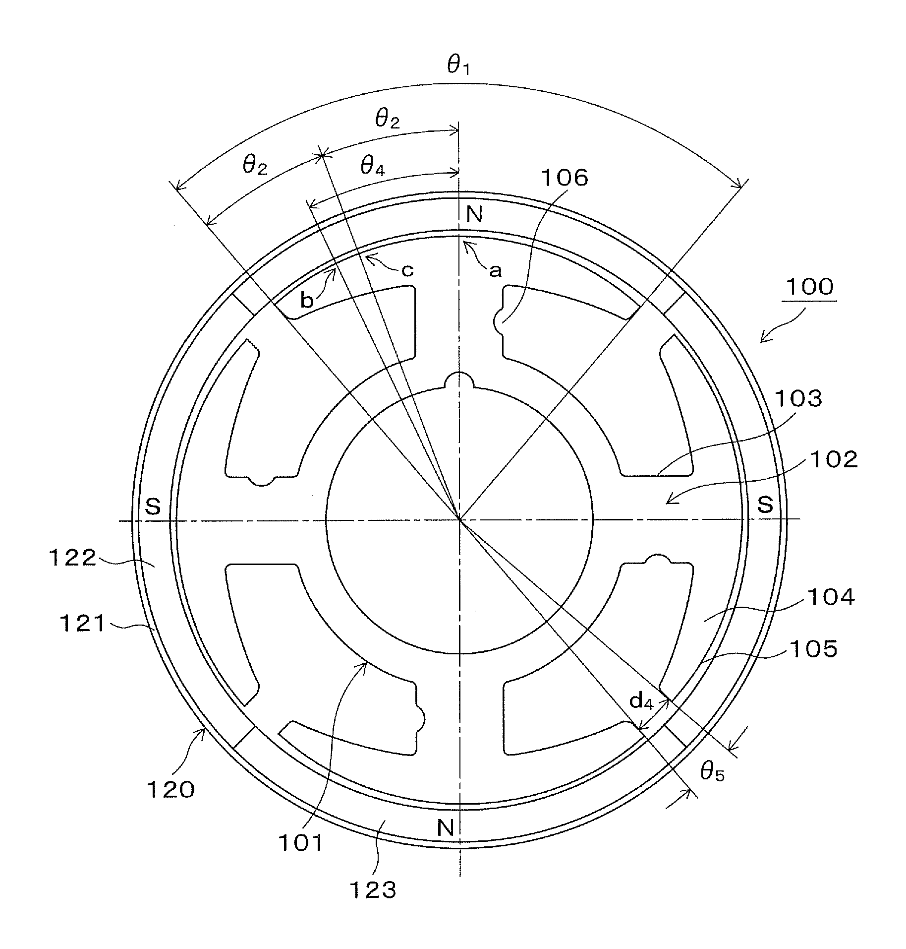
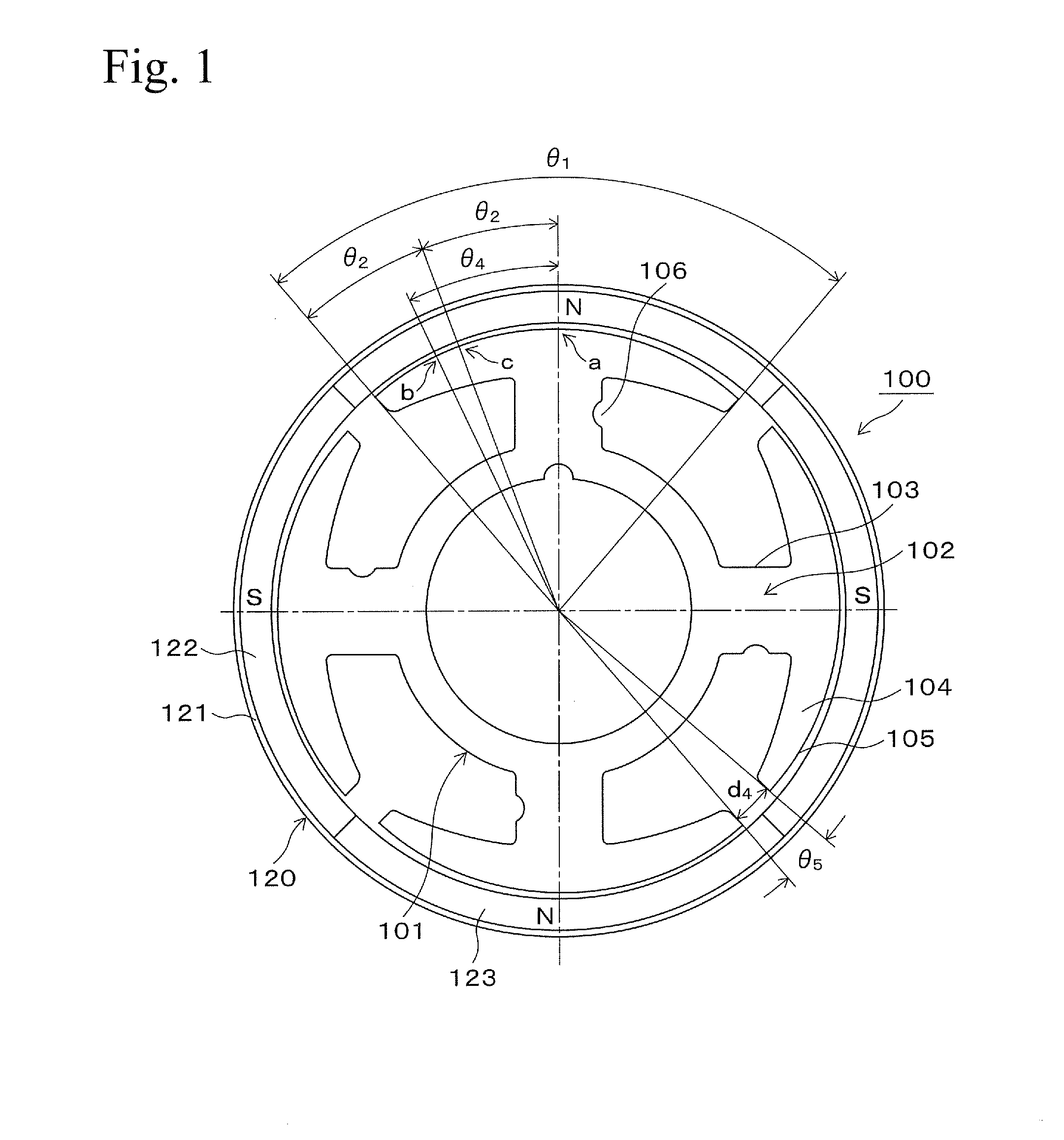
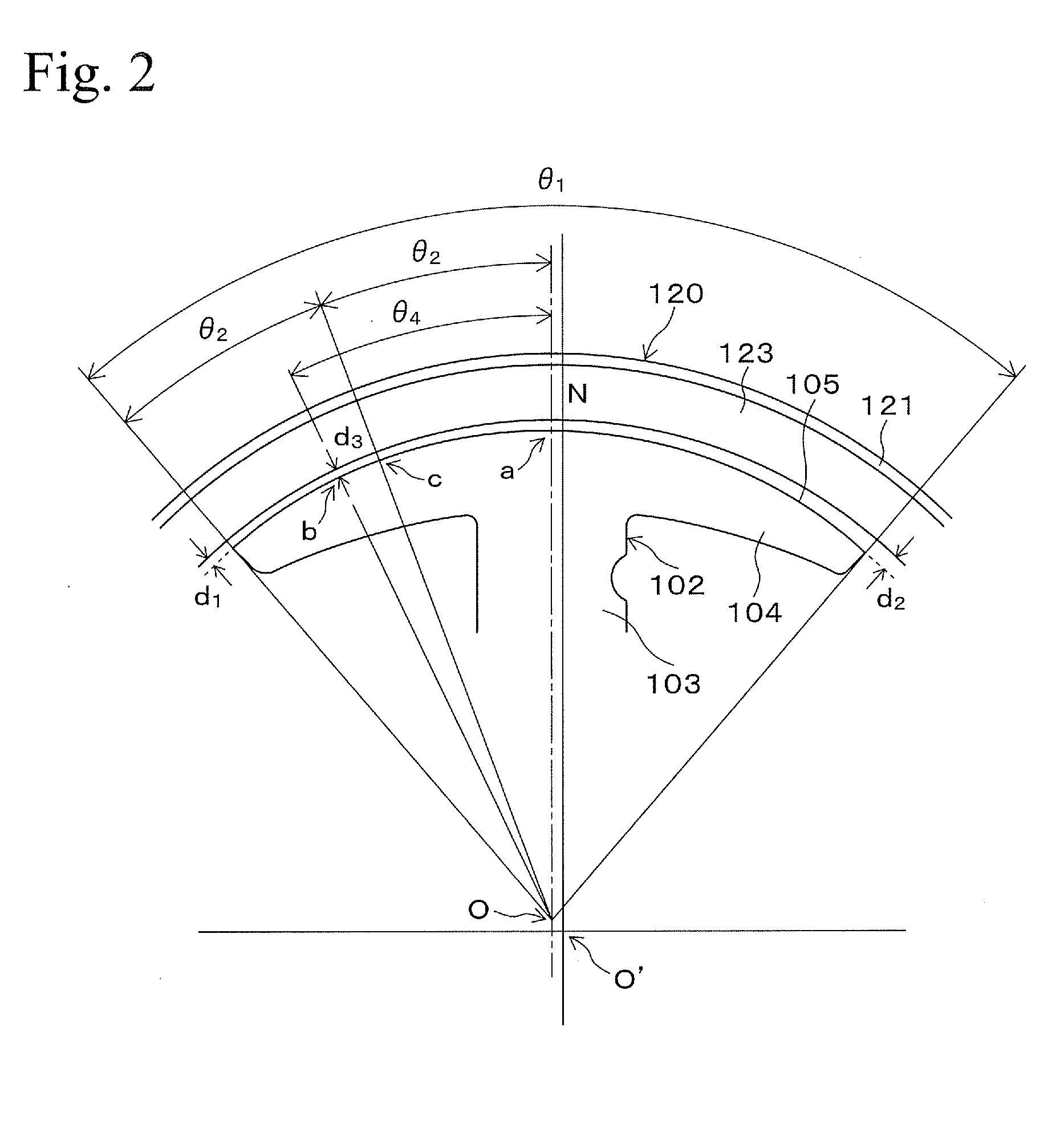
[0018]FIG. 1 shows a single-phase brushless motor 100. The single-phase brushless motor 100 is an outer-rotor-type single phase brushless motor. The single-phase brushless motor 100 has a stator core 101.

[0019]FIG. 3 is a perspective view showing the stator core 101. The stator core 101 is formed by laminating a plurality of thin plates of magnetic material (for example, electrical steel, etc.) processed in a shape shown in FIG. 1. The stator core 101 has four salient poles 102. The salient pole 102 contains an extending portion 103 which extends in an outer direction from an axial center (rotational center), a tip portion 104 which exists at a tip of the extending portion and has a structure which is an opened umbrella shape when it is viewed from an axial direction, and a salient pole surface 105 which is an outer surface of the tip portion 104 and faces to inner circumference surface of a rotor described below via a gap. Stator coils (driving coils), not shown in t...


PUM


Abstract

A single-phase brushless motor has both superior start-up stability and low cogging torque. In the outer-rotor-type single-phase brushless motor, when a gap width between the rotor and one edge of the salient pole surface is defined as d1, a gap width between the rotor and the other edge of the salient pole surface is defined as d2, and a minimum gap width between the rotor and the salient pole surface is defined as d3, the formula d3<d1<d2 is satisfied, and the gap width is d3 at a position shifted toward the one edge of the salient pole surface from the center of the arc shape which forms the salient pole surface.

Description

BACKGROUND OF THE INVENTION[0001]1. Field of the Invention[0002]The present invention relates to a single-phase brushless motor in which a salient pole of a stator has a specific structure.[0003]2. Related Art[0004]A structure of a salient pole of a stator core in an outer-rotor-type single-phase brushless motor, in which at both end portions in a rotation direction, a gap width is continuously varied in a rotation direction, so that a gap between a rotor and one end portion is made minimum and a gap between the rotor and the other end portion is made maximum, is disclosed in Japanese Patent Application Laid-Open No. 2006-333585.[0005]In the single-phase brushless motor, there is a problem in which both superior start-up stability and low cogging torque are required. The start-up stability means a characteristic in which stable start occurs when electrifying is started from a stopped state. In order to obtain the start-up stability, it is effective that a tip shape of the salient po...

Claims


Application Information

Patent Timeline
Patent Type & Authority Applications(United States)
IPC IPC(8): H02K1/14
CPCH02K1/14H02K29/03H02K1/146H02K2213/03
Inventor OMURA, YUJINAKANO, TOMOAKINISHIZAWA, MASAAKISAKAGUCHI, TAKAHIROUCHIKAWA, SHINICHITSUKADA, TOMOYUKI
Owner MINEBEAMITSUMI INC
Why Eureka
Try Eureka