

Coin sorting apparatus
a sorting apparatus and coin technology, applied in the direction of coin freed or similar apparatuses, coin inlets, instruments, etc., can solve the problems of limited sorting methods, difficult coin sorting for the conventional sorting apparatus, and the foregoing problem in the conventional coin sorting apparatus becomes more serious, and achieves efficient coin recovery
- Summary
- Abstract
- Description
- Claims
- Application Information
AI Technical Summary
Benefits of technology
Problems solved by technology
Method used
Image

Examples
first embodiment
[0129
[0130]The general construction of the first embodiment, the respective constructions of component units, and operations, functions and effects of the first embodiment will be described in that order with reference to FIGS. 1 to 12b.
[0131][General Construction]
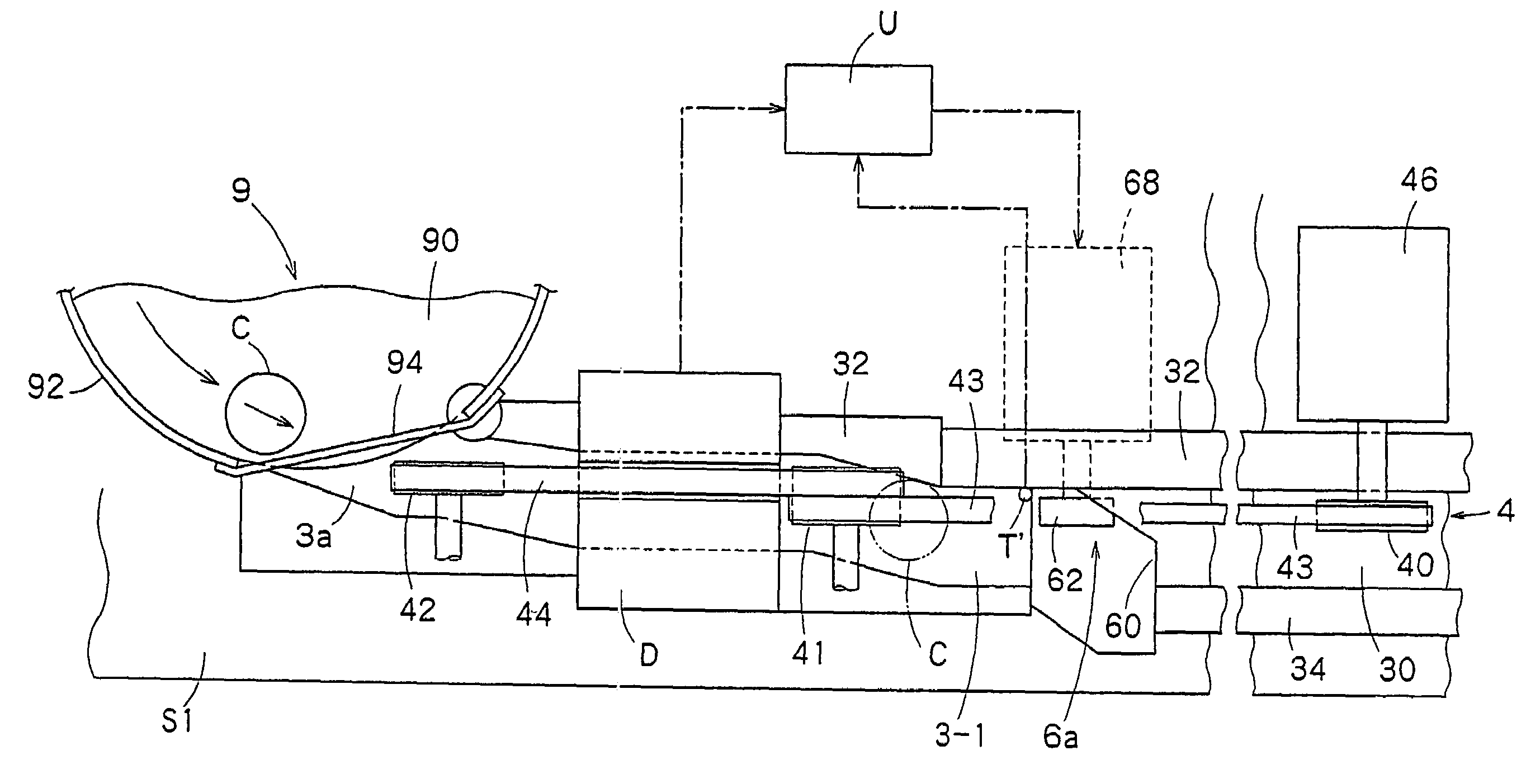
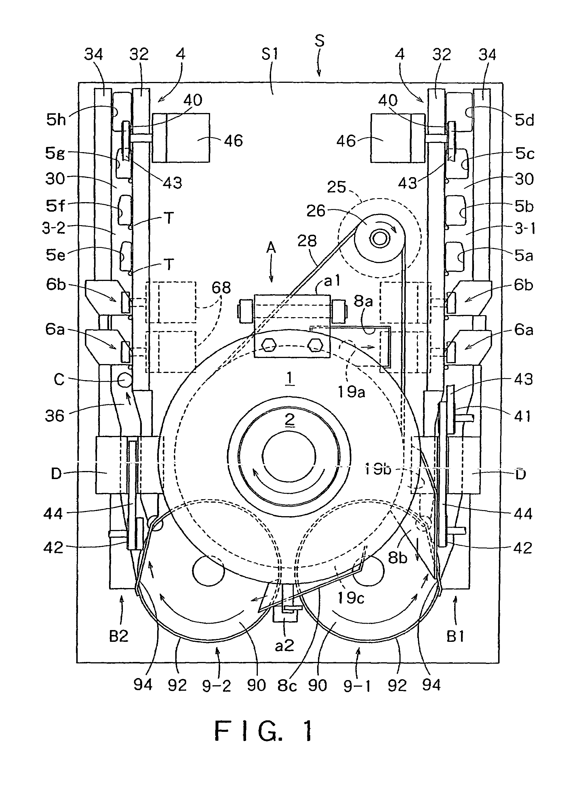
[0132]A coin receiving system in this embodiment is provided with a coin sorting apparatus s shown in FIG. 1 to sort coins of mixed denominations by denomination. The coin sorting apparatus S includes a presorting unit or mechanism (presorting means) A for sorting coins into three groups, and two main sorting lines or units (main sorting means) B1 and B2 for sorting coins of the two groups by denomination, respectively.
[0133]The coin receiving system in this embodiment is intended to deal with coins of mixed currency units including Euro coins of eight denominations, and “different coins”, such as old coins, i.e., old-denomination coins, to be replaced with Euro coins. Euro coins are those of eight denominations that can ...
second embodiment
[0249
[0250]A coin sorting apparatus in a second embodiment according to the present invention will be described with reference to FIGS. 37 to 40. The coin sorting apparatus in the second embodiment is provided with a rotary disk 2′ basically the same as the rotary disk 2′ (FIG. 28) of the coin sorting apparatus in the sixth modification of the first embodiment.
[0251]Referring to FIG. 37, the rotary disk 2′ has a disk body 22′ supported by a shaft 20 for rotation, a resilient member 200 having the shape of a laminated disk and attached to the upper surface of the disk body 22′. As shown in FIGS. 37 and 38, the resilient member 200 has a thin urethane rubber layer 201 and a porous resilient layer 206 underlying the urethane rubber layer 201. Preferably, the porous resilient layer 206 is formed of rubber sponge (foam rubber) having a comparatively high impact resilience of, for example, a compression load in the range of about 630 to about 950 g / cm2 at 25% compression.
[0252]As shown in...
third embodiment
[0262
[0263]A coin receiving system in a third embodiment according to the present invention will be described with reference to FIGS. 41 to 44. The coin receiving system in the third embodiment is provided with a coin sorting apparatus similar to the coin sorting apparatus in the first embodiment. In FIGS. 41 to 44, parts like or corresponding to those of the coin sorting apparatus in the first embodiment shown in FIGS. 1 to 12b will be denoted by the same reference characters, and reference will be made to FIGS. 1 to 12b when necessary. Description of mechanisms and operations identical with those of the first embodiment will be partly or entirely omitted. The construction, operation, function, effect and modification of the third embodiment will be described in sequence.
[0264][Construction]
[0265]The coin receiving system is intended to receive mixed coins including Euro coins of a new currency unit (new coins) and coins of old currency units, such as those of European currencies i...
PUM
 Abstract
Description
Claims
Application Information