Portable car ramp

a car ramp and car technology, applied in the direction of inclined ship lifting, lifting devices, construction, etc., can solve the problems of difficult movement of wheels around during use and/or storage, and generate horizontal vector forces, so as to reduce possible wheels

Inactive Publication Date: 2006-02-28
CENCOR PLASTICS
View PDF13 Cites 46 Cited by
  • Summary
  • Abstract
  • Description
  • Claims
  • Application Information

AI Technical Summary

Benefits of technology

[0009]Yet another object of this invention is to provide a friction pad fixed to the underside of the inclined run component suited to rest on the support medium and resist sliding of the inclined run component along the support medium when wheel weight is on the inclined run. The pad further might be part of an elongated mat aligned with and extended away from the inclined run to have the vehicle wheel on the mat when first rolling up the inclined run, for further precluding the inclined run component from sliding along the support medium before and as the wheel rolls up the inclined run.
[0010]A further object of this invention is to provide the elevated wheel run component with no underside friction means that will engage the support medium, so that wheel weight transfer from the inclined run component to the elevated run component might allow ramp sliding along the support medium for reducing possible wheel override off of the elevated run.

Problems solved by technology

One problem associated with car ramp use is that when the wheel weight is on the inclined run, particularly when the wheel is being rolled up the inclined run, horizontal vector forces are generated against the ramp tending to slide it along the support medium in the direction away from the vehicle.
A further drawback of many known car ramps is their bulky size and / or heavy weight, making it difficult to move them about during use and / or to store them.

Method used


Image

  • Portable car ramp
  • Portable car ramp
  • Portable car ramp

Examples


Embodiment Construction

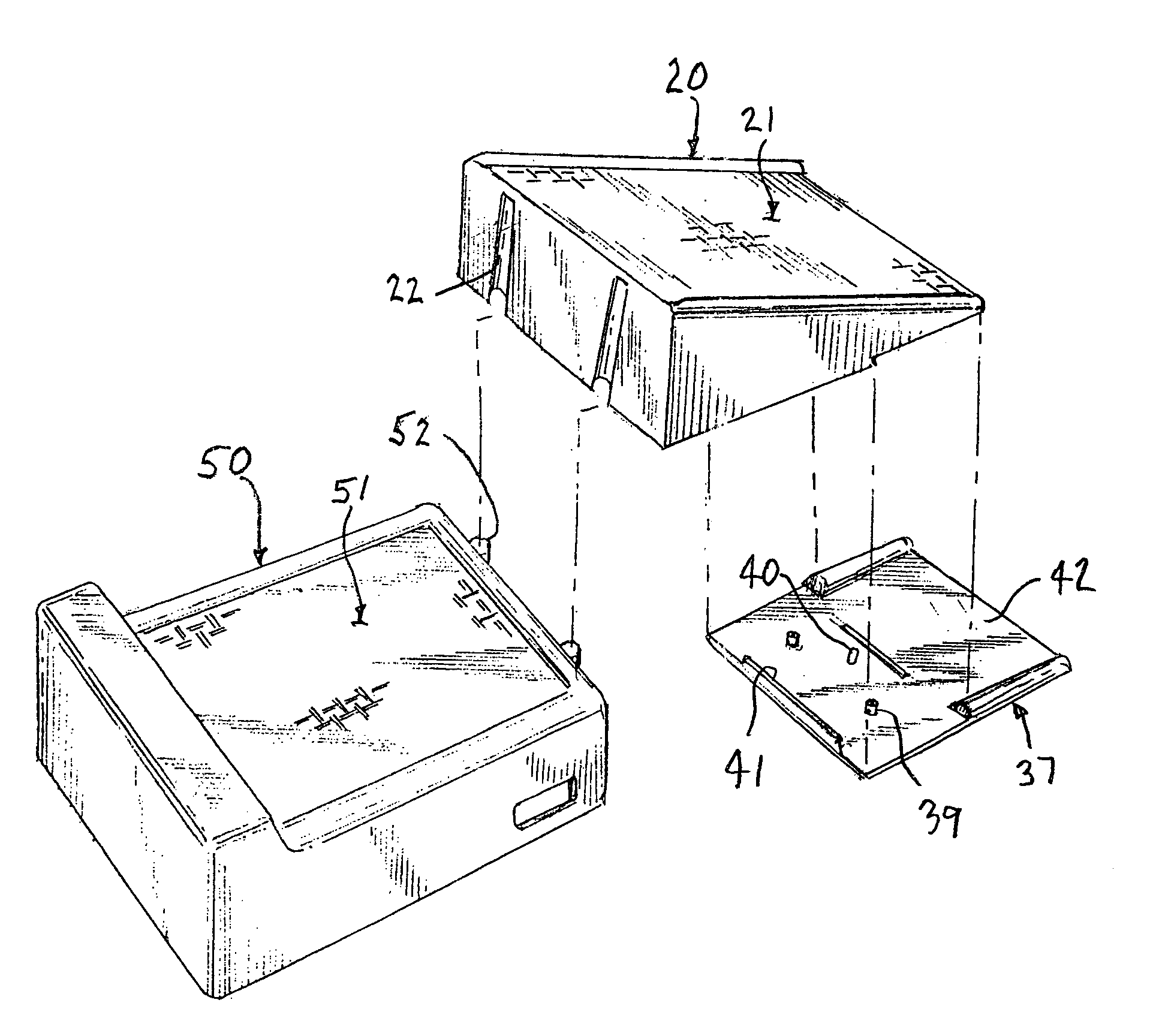
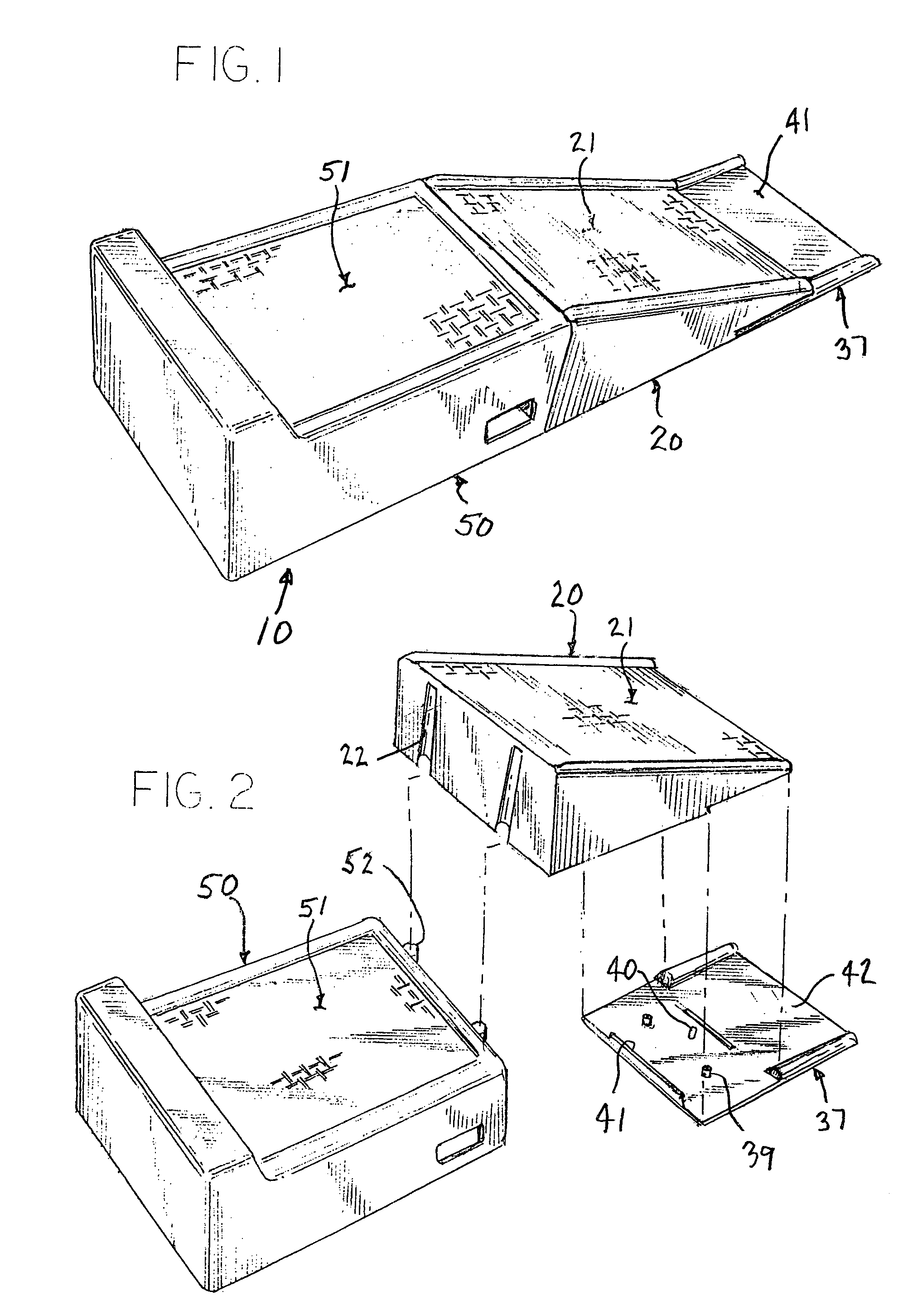
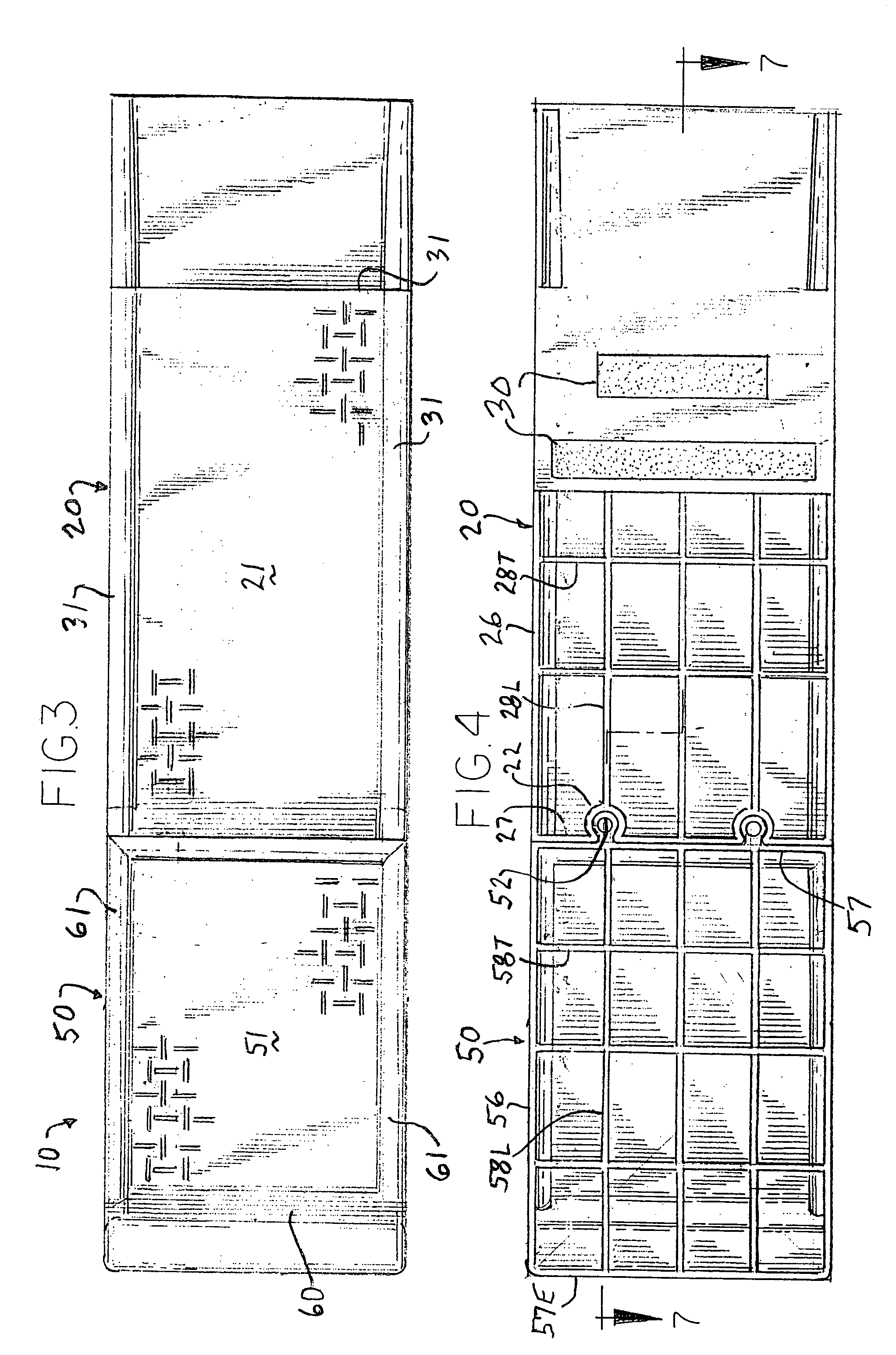
[0019]The illustrated portable car ramp 10 is made is made up of two major structural components 20, 50, respectively having thereon an inclined wheel run 21 and an elevated wheel run 51. The components 20, 50 have cooperating telescoping socket and pin formations 22, 52 adapted to separably couple the components 20, 50 together longitudinally of the wheel runs 21, 51, while allowing limited freedom of movement otherwise.

[0020]When the components 20, 50 are coupled, bottom edges 23, 53 (see FIG. 7) on the respective components laterally lie generally along a single plane suited to be stable when positioned on a generally flat surface 12, such as a garage floor, driveway, or like support medium. The inclined and elevated wheel runs 21, 51 are then longitudinally aligned, meeting along corner edge 24; while inclined wheel run 21 terminates at its lower end just above the support medium 12.

[0021]The elevated wheel run 51 and the bottom edge 53 of component 50 should be extended along s...


PUM


Abstract

This portable car ramp has two structural components coupled longitudinally together, while allowing limited relative vertical movement when each's bottom edge rest on a medium surface. The first component has an elevated wheel run while the second component has an inclined wheel run. When coupled together, the component wheel runs are longitudinally aligned, meeting at a corner, so that a vehicle wheel can roll up the inclined run, over the corner, and onto the elevated run, and vice-versa. Friction pads fixed to the second component bottom edge increase resistance against ramp sliding along the medium surface, particularly with the wheel supported on the inclined wheel run. The first component has no bottom edge friction pads so that car ramp sliding along the medium surface is possible, such as should the wheel be rolled against a stop on the elevated wheel run.

Description

BACKGROUND OF THE INVENTION[0001]Portable car ramps are used for increasing vertical clearance beneath a vehicle having its wheels otherwise supported on a flat horizontal garage floor, driveway, or like support medium, so that a worker can repair, or service the vehicle from the underside thereof.[0002]A typical portable car ramp will have bottom structure that can be rested in a stable manner on the support medium, a generally level wheel run extended substantially parallel to but elevated above the support medium, and an inclined wheel run extended between one end of the elevated wheel run and the support medium. The vehicle wheel can be rolled up the inclined run to the elevated run, and along it until restrained by a stop adjacent the opposite run end.[0003]Popular portable car ramps might be about a foot wide, three to six feet long, and provide vertical wheel lifts between possibly six and fifteen inches with the inclined runs pitched between possibly ten and twenty five degr...

Claims


Application Information

Patent Timeline
Patent Type & Authority Patents(United States)
IPC IPC(8): E02C3/00B66F7/24E01D1/00
CPCB66F7/243
Inventor BERG, JOEL J.
Owner CENCOR PLASTICS
Why Eureka
Try Eureka