Press brake tooling technology

a technology of press brakes and tools, applied in the field of press brakes and press brake tools, can solve the problems of tools that are not adapted for being dismounted from the tool holder, and the tools are not adapted for being dismounted

Active Publication Date: 2006-04-04
WILSON TOOL INT
View PDF41 Cites 39 Cited by
  • Summary
  • Abstract
  • Description
  • Claims
  • Application Information

AI Technical Summary

Benefits of technology

[0010]In certain embodiments, the present invention provides a press brake tool that is adapted for being mounted in a tool holder by moving the tool vertically into a channel defined by the tool holder This tool is adapted for being dismounted from the tool holder by moving the tool horizontally out of the channel. The tool, however, is not adapted for being dismounted from the tool holder by moving the tool vertically out of the channel. The tool has a shank provided with a safety key. In the present embodiments, the safety key is biased toward an extended position when the shank is moved to an operative position in the channel of the tool holder. Preferably, the tool here has no externally accessible actuator for retracting the safety key, such that once the tool's shank is moved into its operative position in the channel of the tool holder a press brake operator is prevented from retracting the safety key and removing the tool vertically from the tool holder.

Problems solved by technology

The tool, however, is not adapted for being dismounted from the tool holder by moving the tool vertically out of the channel.
However, the tool is not adapted for being dismounted by moving the tool vertically out of the channel.

Method used


Image

  • Press brake tooling technology
  • Press brake tooling technology
  • Press brake tooling technology

Examples


Embodiment Construction

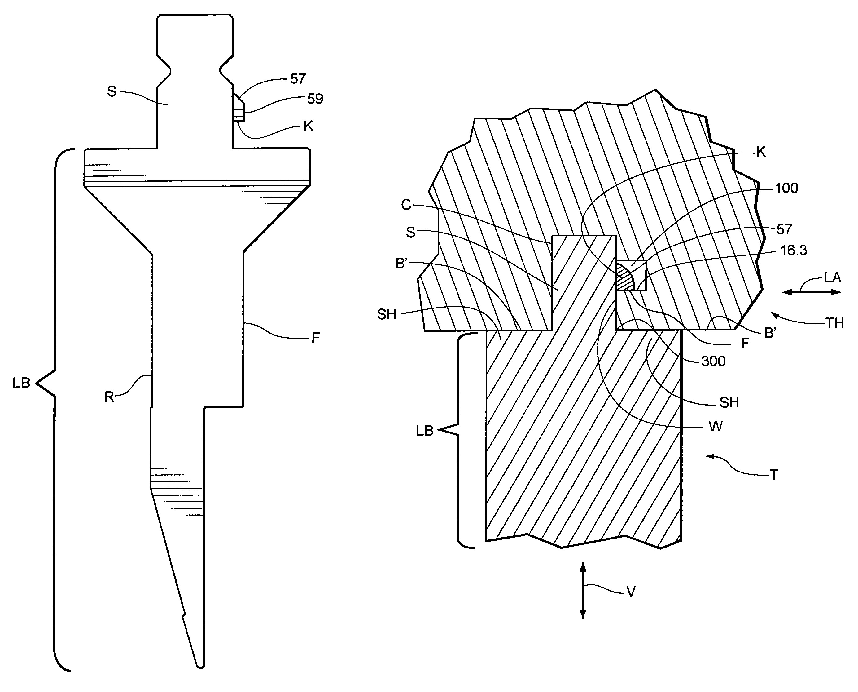
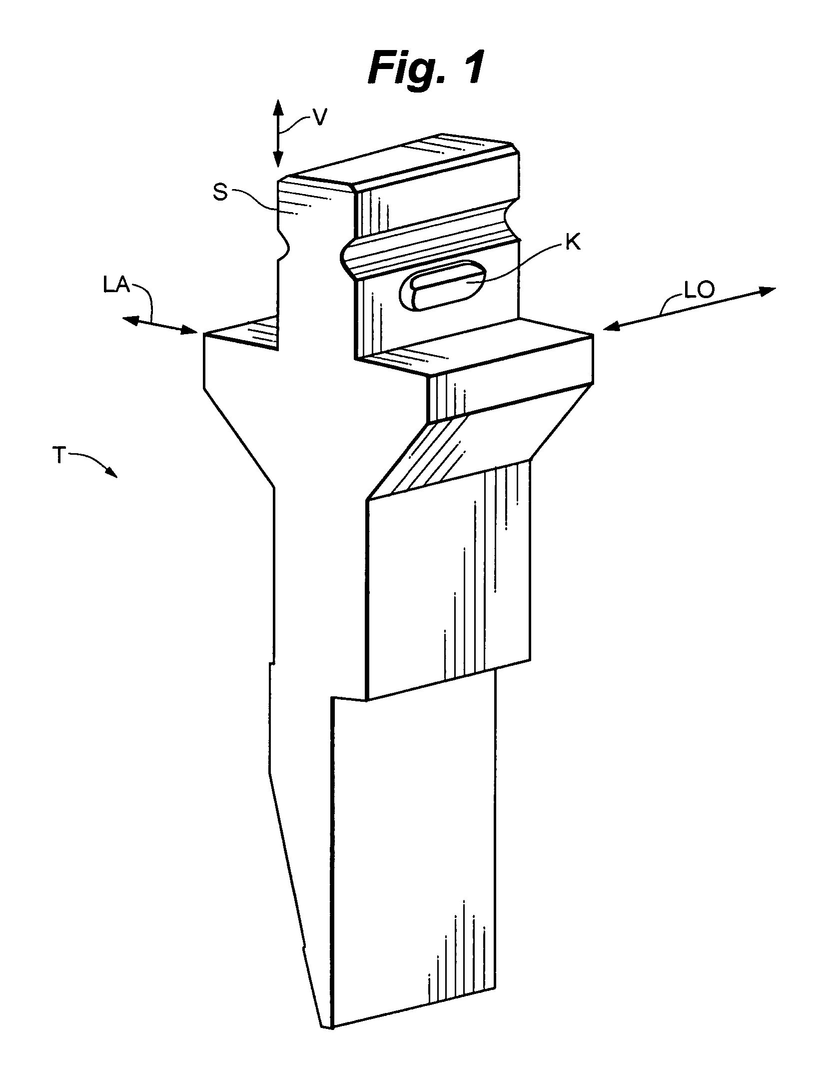
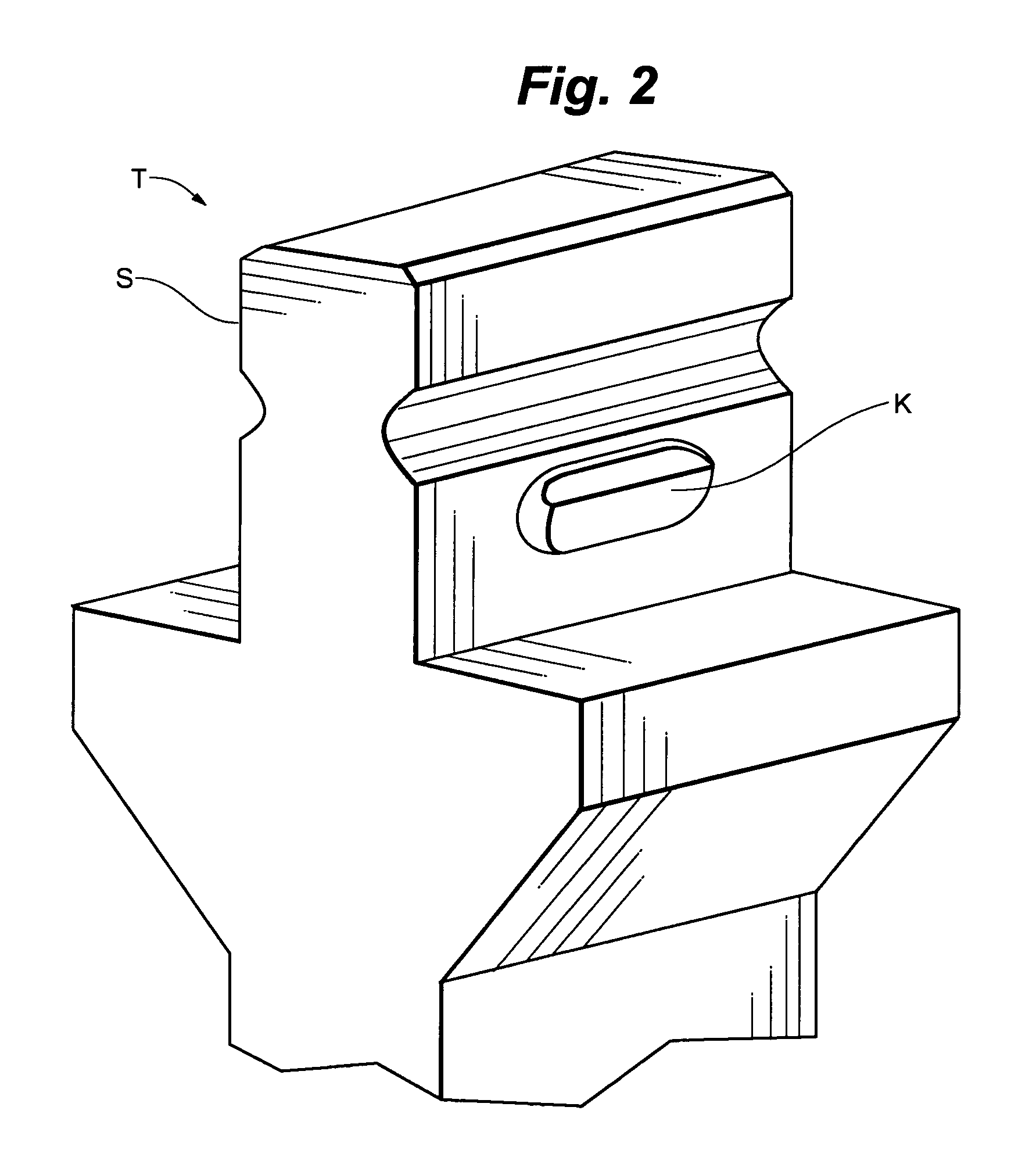
[0039]The invention provides press brake tools that are adapted for being mounted on a tool holder by moving the tool vertically into a channel defined by the tool holder, and for being dismounted from the tool holder by moving the tool horizontally (i.e., by sliding the tool lengthwise) out of the channel. Press brake tools of this nature are referred to herein as click-in / slide-out tools. Preferably, when these tools are mounted in the tool holder they produce an audible “click” sound upon reaching their operative position. In preferred embodiments, this sound results when the safety key(s) on the tool snaps into place in a safety slot defined by the tool holder, as detailed below. It is to be understood that this audible clicking is a preferred feature, which is by no means required for all embodiments of the invention.

[0040]The Wila tool described above is a click-in / click-out tool. In other words, it is adapted for both vertical mounting (i.e., mounting by moving the tool verti...


PUM

PropertyMeasurementUnit
longitudinal lengthaaaaaaaaaa

Abstract

The invention provides press brake and press brake tooling technology. Certain embodiments of the invention provide a press brake tool that has an elongated, retractable safety key. In certain embodiments, the invention provides click-in / slide-out press brake tools. In some of these embodiments, the tool has a safety key defining a flat (i.e., a planar wall section / planar surface) that is adapted for sliding along a surface of a tool holder when the tool is dismounted from the holder by moving the tool horizontally out of the holder. In certain embodiments, the flat has a longitudinal length of at least about 0.008 inch (in some cases, at least about 0.010 inch, at least about 0.015 inch, or at least about 0.020 inch), ranging up to the full longitudinal length of the tool. In certain embodiments, the invention provides a press brake tool and a tool holder in combination. Finally, the invention in some embodiments provides methods of press brake operation.

Description

FIELD OF THE INVENTION[0001]The present invention relates generally to industrial presses and tools. More particularly, this invention relates to press brakes and press brake tools.BACKGROUND OF THE INVENTION[0002]Press brakes are commonly used to bend sheet-like workpieces, such as sheet metal. A conventional press brake has an upper beam and a lower beam, at least one of which is movable toward and away from the other. Typically, the upper beam is movable vertically while the lower beam is fixed in a stationary position. It is common for a male forming punch and a female forming die to be mounted respectively on the upper and lower beams of a press brake.[0003]Typically, the punch has a downwardly-oriented, workpiece-deforming surface (or “tip”). The configuration of this surface is dictated by the shape into which it is desired to bend a workpiece. The die typically has a recess that is aligned with the tip of the punch. The configuration of this recess corresponds to the configu...

Claims


Application Information

Patent Timeline
Patent Type & Authority Patents(United States)
IPC IPC(8): B21D37/04B21D5/02
CPCB21D5/0209B21D37/04B21D5/0236
Inventor HARRINGTON, HEATH E.CAMPBELL, PATRICK J.JOHNSON, PAUL T.ROGERS, BRYAN L.
Owner WILSON TOOL INT
Why Eureka
Try Eureka