Iron golf club and golf club set with variable weight distribution

a golf club and variable weight technology, applied in golf clubs, racket sports, sport apparatus, etc., can solve the problems of extending the effective face length of the golf club head and the groove of the golf club

Inactive Publication Date: 2006-04-04
MIZUNO CORPORATION
View PDF32 Cites 80 Cited by
  • Summary
  • Abstract
  • Description
  • Claims
  • Application Information

AI Technical Summary

Benefits of technology

[0007]The present invention meets the needs described above in an iron golf club head. Generally described, the invention includes an iron golf club head having a cavity, a face portion for striking a golf ball, a heel portion, a toe portion, a top portion and a sole portion. The iron golf club head also includes a raised wall portion extending upward from the sole portion and offset from the portion to lower the center of mass down toward the sole portion and backwards away from the cavity. The iron golf club head further includes a tapered weight within the cavity that extends upward from the sole portion. The tapered weight has a thickness that is tapered from the toe portion to the heel portion so that the thickness of the tapered weight is thicker towards the toe portion than toward the heel portion to provide a more solid feel on off-center hits toward the toe of the iron golf club.
[0008]The iron golf club may further include a groove extending between the raised wall portion and the cavity and set at an oblique angle from the face portion so that it is parallel the tapered weight. The groove allows a greater amount of weight to be distributed to the raised wall portion, thereby moving the center of mass depth farther away from the face portion, and thus increasing the effective loft of the iron golf club head. The groove may also lengthen the effective face length of the iron golf club head. Here, the effective face length refers to a length of a portion of the face portion that can flex when striking a golf ball and is defined to be a length in the direction from the sole portion toward the top portion of the iron golf club.
[0009]The iron golf club may further include a cavity pad located within the cavity and extending from the top of the tapered weight upward to the top of the cavity to reinforce the upper cavity and reduce unwanted vibrations that may occur during the striking of a golf ball.

Problems solved by technology

The groove may also lengthen the effective face length of the iron golf club head.

Method used


Image

  • Iron golf club and golf club set with variable weight distribution
  • Iron golf club and golf club set with variable weight distribution
  • Iron golf club and golf club set with variable weight distribution

Examples


Embodiment Construction

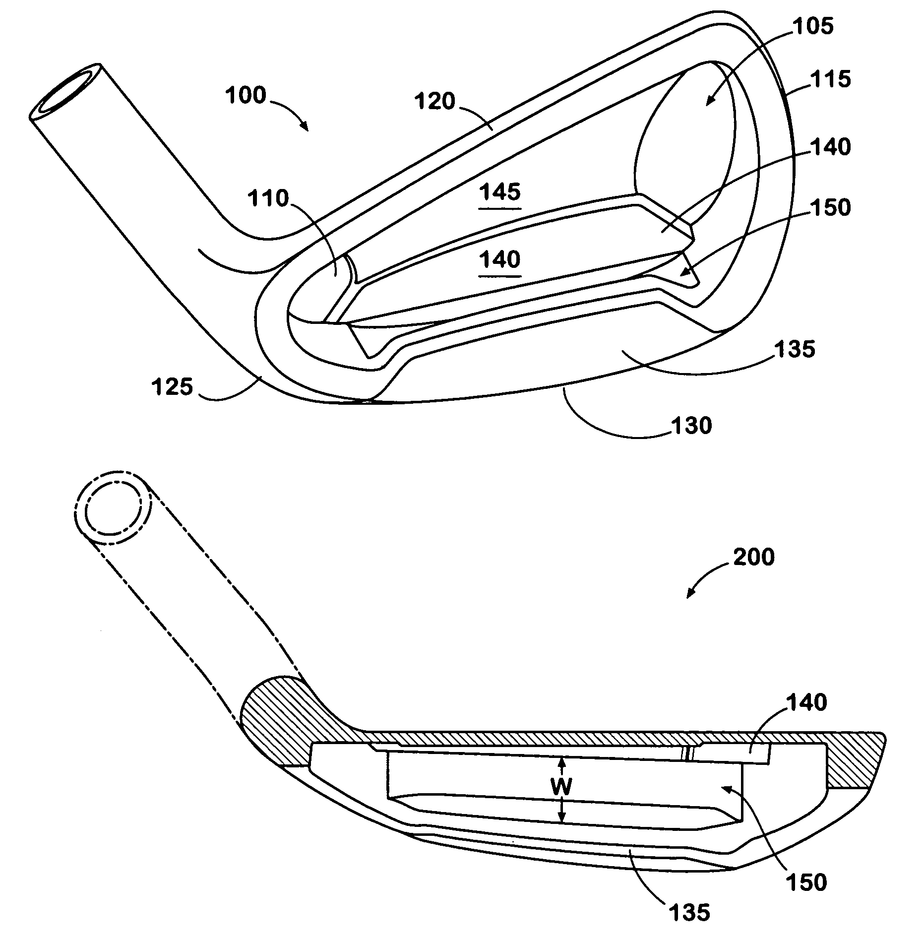
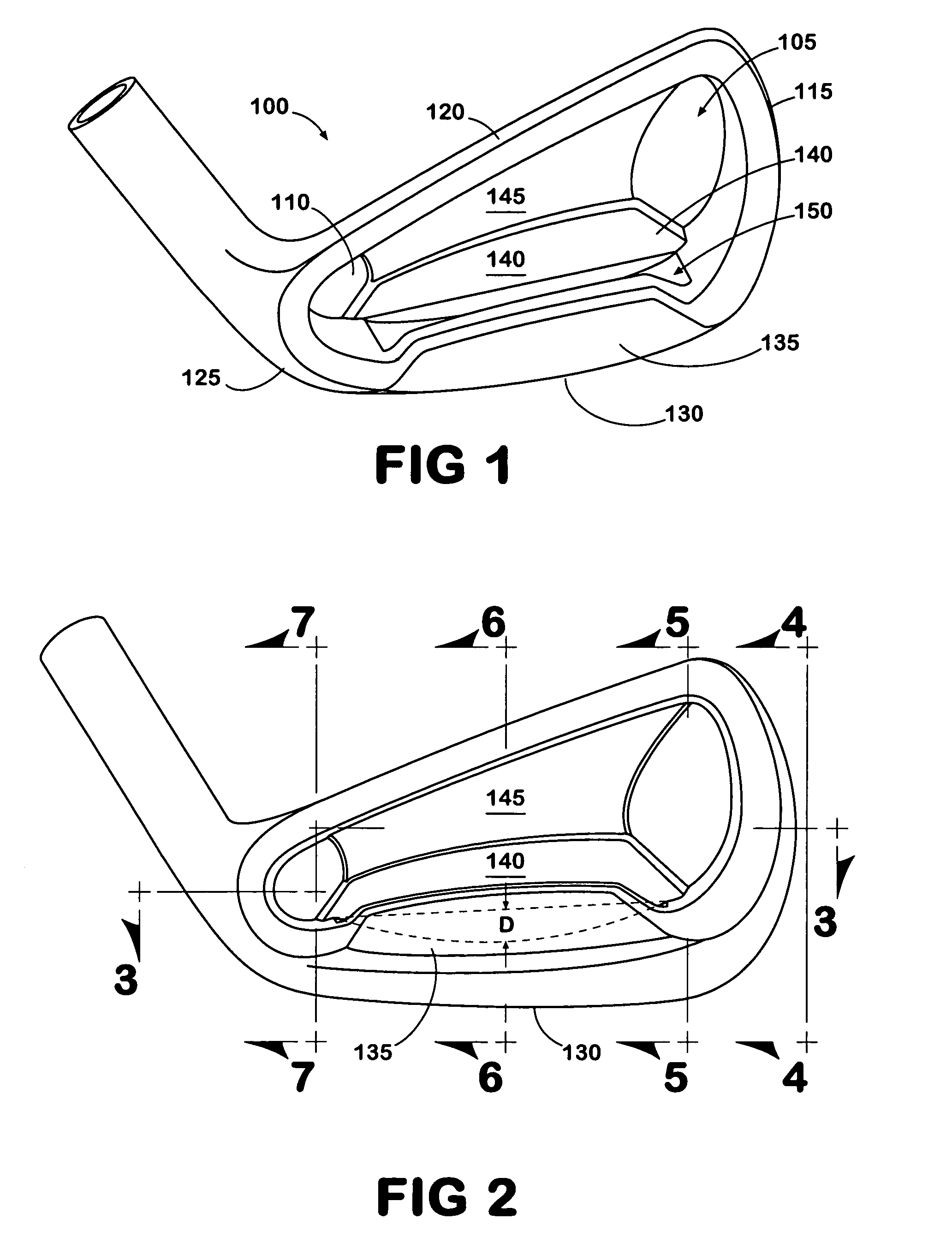
[0030]FIG. 1 is a diagram illustrating a bird's eye view of an iron golf club head 100 in accordance with some embodiments of the present invention. The iron golf club head 100 may include a cavity 105, which contains a back wall 110 and is surrounded by a toe portion 115, a top portion 120, a heel portion 125 and a sole portion 130. The iron golf club head 100 may also includes a face portion (not shown), which is used for striking a golf ball.

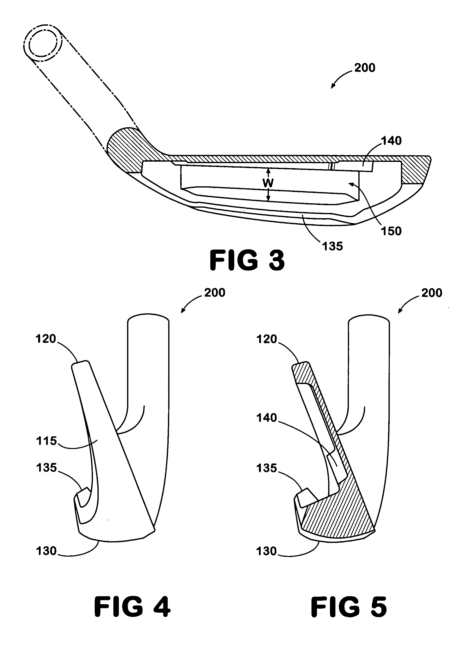
[0031]The back wall 110 of the cavity 105 may include a tapered weight 140 that may be positioned toward the sole portion 130 within the cavity 110. The tapered weight 140 may have a predetermined length, which is less than the length of the cavity 105 and may extend along an axis extending from the toe portion 115 to the heel portion 125. The tapered weight 140 is positioned directly behind the ball hitting portion of the face portion to provide a high coefficient of restitution (COR), which is typically greater than 0.8. The length of the t...


PUM


Abstract

An iron golf club and a set of iron golf clubs that have a variable weight distribution. Each iron golf club head has a cavity and a raised wall portion that extends upward from the sole and offset from the cavity. The raised wall portion is separated from the cavity by a groove set at an oblique angle to the face portion of the iron golf club The groove deepens the center of mass depth and lengthens the effective face length of the iron golf club. The width of the groove may vary between each golf club in a set of iron golf clubs, such that the width of the groove of the long irons is greater that the width of the groove of the middle irons, and the width of the groove of the middle irons is greater than the width of the groove of the short irons.

Description

CROSS-REFERENCE TO RELATED APPLICATIONS[0001]This application is a Continuation-in-Part of U.S. patent application Ser. No. 10 / 757,131 filed on Jan. 14, 2004, which is a Continuation Patent Application of U.S. patent application Ser. No. 09 / 976,496 filed on Oct. 12, 2001 now U.S. Pat. No. 6,709,345, which claims priority from Japanese Patent Application Serial No. 2000-314678 filed on Oct. 16, 2000.TECHNICAL DESCRIPTION OF THE INVENTION[0002]The present invention is directed to an iron golf club head and more particularly to a cavity-back iron golf club head having raised wall portion, which is offset from the cavity and a variable width groove that increases the center of gravity depth of the iron golf club head and increases the effective hitting surface.BACKGROUND[0003]Perimeter weighted iron golf club heads have become increasingly popular with golfers since they were first introduced in the 1980's. The cavity-back iron golf club head moved most of the weight that was located be...

Claims


Application Information

Patent Timeline
Patent Type & Authority Patents(United States)
IPC IPC(8): A63B53/04A63B53/00
CPCA63B53/04A63B53/047A63B2053/005A63B2053/0408A63B2053/0491A63B2053/0458A63B2053/0433A63B60/02A63B53/005A63B53/0408A63B53/0433A63B53/0458A63B60/00
Inventor NAGAI, MASAOLLEWELLYN, DAVID G.TAYLOR, HARRY B.SARAIE, MAMORUTOSHINARI, ISAMU
Owner MIZUNO CORPORATION
Why Eureka
Try Eureka