Prying tool with positionable handle

a technology of lifting tool and handle, which is applied in the direction of multi-purpose tools, crowbars, lifting devices, etc., can solve the problems of heavy, bulky, and inability to use in tight situations, and present pry tools are somewhat heavy

Inactive Publication Date: 2006-04-11
WHELAN PATRICK J
View PDF7 Cites 39 Cited by
  • Summary
  • Abstract
  • Description
  • Claims
  • Application Information

AI Technical Summary

Problems solved by technology

Although useful, present pry tools are somewhat he

Method used


Image

  • Prying tool with positionable handle
  • Prying tool with positionable handle
  • Prying tool with positionable handle

Examples


Embodiment Construction

[0014]The prying tool according to embodiments of the invention includes a head portion and a handle portion. The handle portion can be positioned relative to the head portion. Additionally, in some embodiments, the handle portion can be separated from the head portion. Embodiments of the invention also include a tool head having an aperture with a predetermined shape that can be mated with a projection from a handle. The predetermined shape of the aperture and projection allows the handle to be attached to the removable head in a variety of positions.

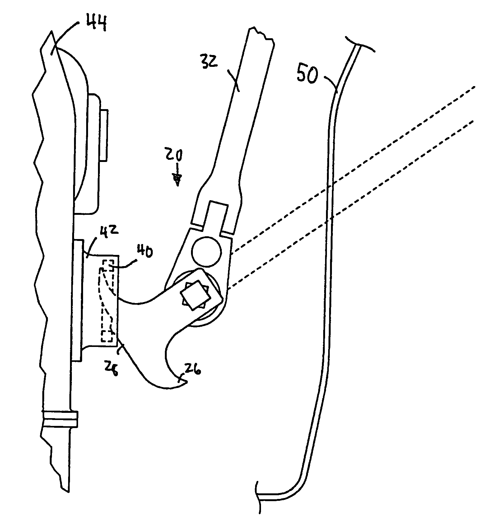
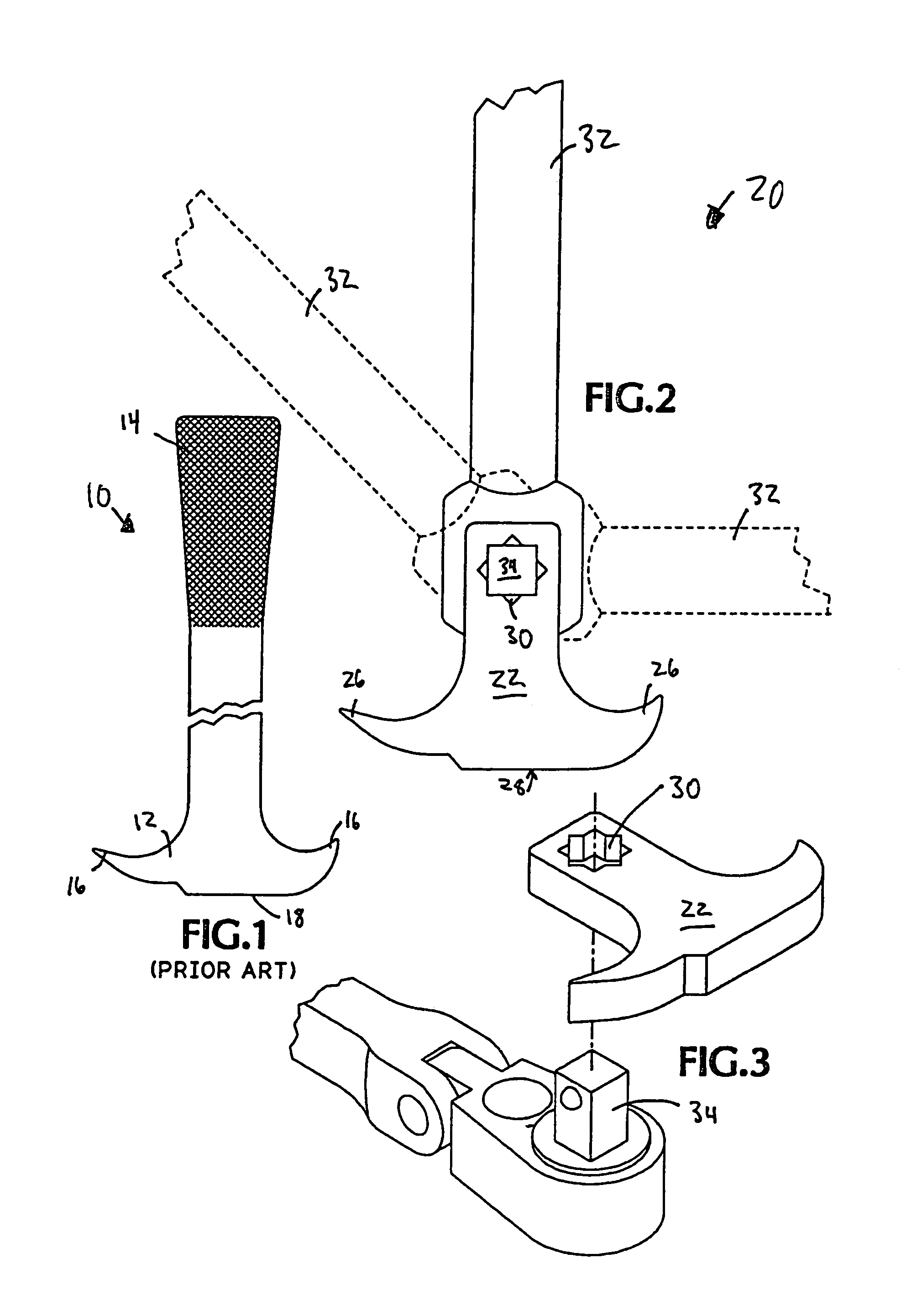
[0015]Referring to FIG. 2, a tool 20 according to embodiments of the invention is shown. The tool 20 includes a head 22 having a pair of working ends 26 and a resting end 28. Additionally, the head 22 has an aperture 30 created therein. A handle 32 includes a projection 34 suitably sized to be insertable into the aperture 30.

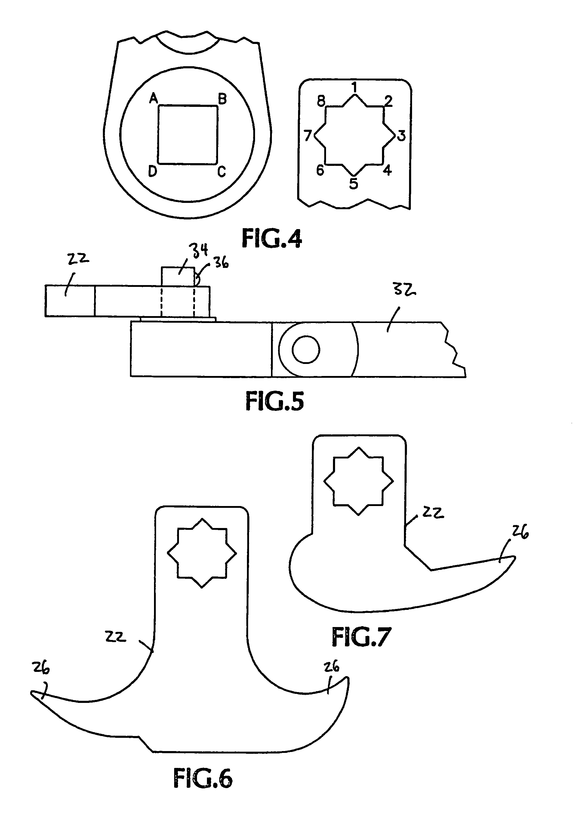
[0016]Preferably, the aperture 30 is formed so that the handle projection 34 may be inserted in a number of diff...


PUM


Abstract

Disclosed is a prying tool having a head portion and a handle portion. The handle portion can be positioned relative to an angle of the head portion. Additionally, in some embodiments, the handle portion can be separated from the head portion. Embodiments of the invention also include a tool head having an aperture with a predetermined shape that can be mated with a projection from a handle. The predetermined shape of the aperture and projection allows the handle to be attached to the removable head in a variety of positions.

Description

[0001]This application claims benefit of Provisional application No. 60 / 417,108 filed on Oct. 8, 2002.TECHNICAL FIELD[0002]This disclosure relates to a prying and lifting tool and, more particularly, to a prying and lifting tool having a positionable handle.BACKGROUND OF THE INVENTION[0003]Prying tools are used in a variety of situations. For instance, they can be used to remove pressed seals such as axel seals, and to remove pulleys and other attachments from shafts, among other uses. As shown in FIG. 1, a prying tool 10 generally has a head end 12 and a handle end 14. The head end 12 further includes one or two working ends 16 that, have a reduced thickness compared to the remainder of the head end. The working ends 16 allow the tool to get under or otherwise provide a lifting or prying point to remove a desired seal or other item. In operation, a user places one of the working ends 16 under the item to be removed, and rests an end 18 on a suitable surface. Once so positioned, the...

Claims


Application Information

Patent Timeline
IPC IPC(8): B66F15/00B25G1/06
CPCB66F15/00B25G1/06B25F1/02
Inventor WHELAN, PATRICK J.
Owner WHELAN PATRICK J
Why Eureka
Try Eureka