System and method for data retrieval in AC power tools via an AC line cord

Inactive Publication Date: 2006-05-30
BLACK & DECKER INC
View PDF75 Cites 29 Cited by
  • Summary
  • Abstract
  • Description
  • Claims
  • Application Information

AI Technical Summary

Problems solved by technology

In the communications mode, the switching action of the switching component is such that the electric motor of the power tool ca

Method used


Image

  • System and method for data retrieval in AC power tools via an AC line cord
  • System and method for data retrieval in AC power tools via an AC line cord
  • System and method for data retrieval in AC power tools via an AC line cord

Examples


Embodiment Construction

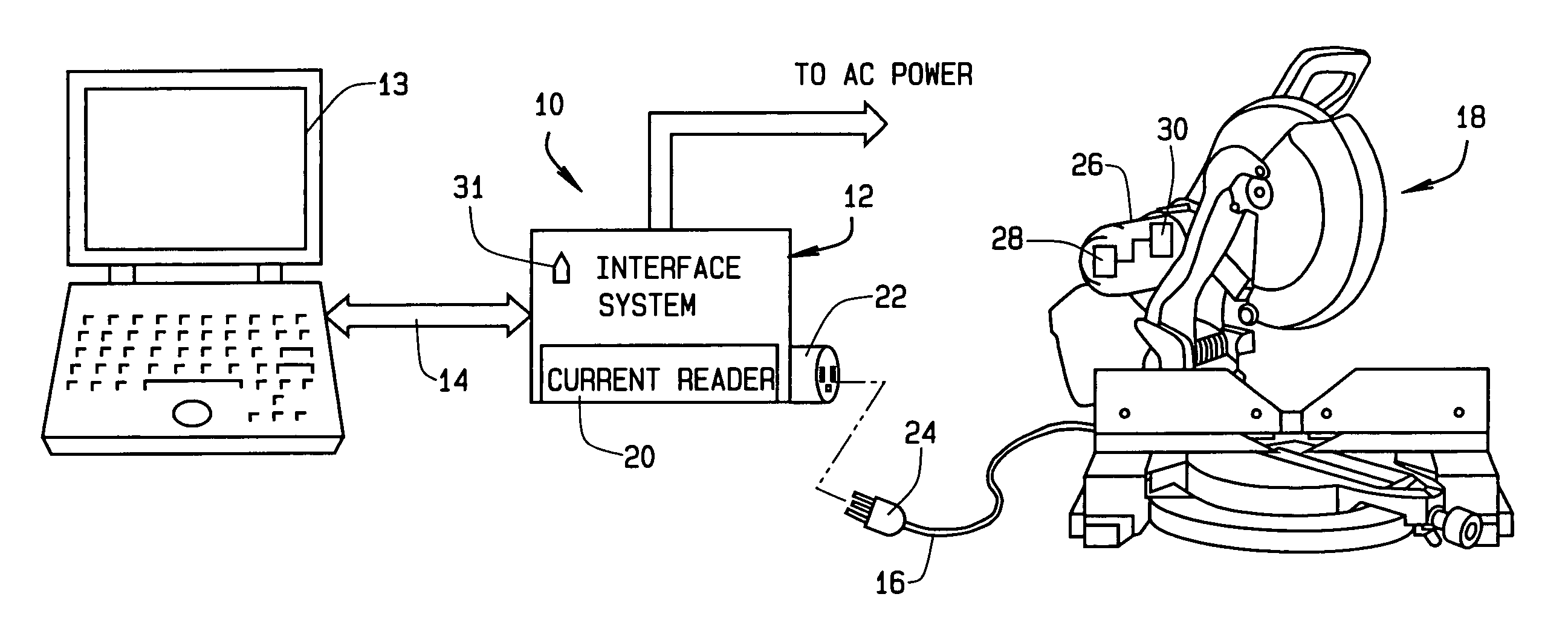
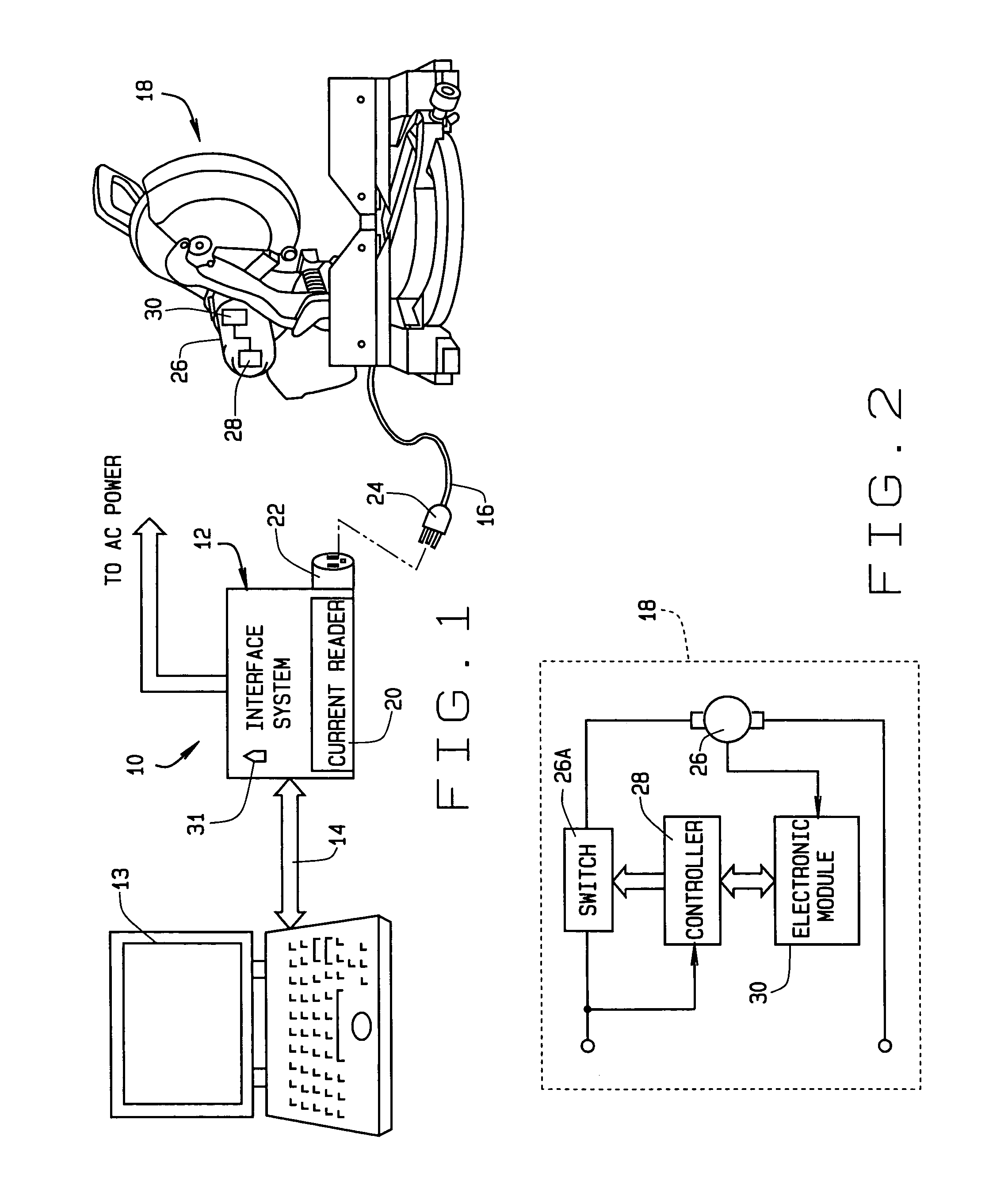
[0014]Referring to FIG. 1, there is shown a system 10 in accordance with a preferred embodiment of the present invention. The system 10 includes an interface subsystem 12 that is coupled to an AC power source. The interface system 12 is further coupled to a computing device 13 or other suitable data logging device via a suitable communications cable 14, and to a power cord 16 of an electrically driven power tool 18. The interface subsystem 12 includes a current reader circuit 20 that will be described in greater detail in the following paragraphs, and an electrical receptacle 22 for receiving a plug 24 of the power cord 16.

[0015]The power tool 18 includes a motor 26 which is controlled by a power switching device 26a in communication with a controller 28. The controller 28 is also in communication with an electronic module 30 housed within the housing of the tool 18. In actual practice, the controller 28 and the electronic module 30 could be provided by a single electronic component...


PUM

PropertyMeasurementUnit
Frequencyaaaaaaaaaa
Frequencyaaaaaaaaaa
Currentaaaaaaaaaa

Abstract

An apparatus and method for obtaining data stored in an electronic module within a power tool over a power line cord of the tool, and without any disassembly of the tool being required. An interface subsystem applies a high frequency, low power AC input signal to the power cord of the tool. A controller within the tool recognizes this signal as an indication that the tool is to be placed in a communications mode. The controller modulates a power switching device used for turning on and off the motor of the tool in such a fashion that current pulses are transmitted over the power line cord back to the interface subsystem. The current pulses correspond to tool usage/performance/identification information stored in the electronic module of the tool. This information is interpreted by a current reader circuit of the interface subsystem as binary information which is then transmitted to an external computing data logging device for analysis and/or recording.

Description

CROSS-REFERENCE TO RELATED APPLICATIONS[0001]This application claims the benefit of U.S. Provisional Application No. 60 / 396,975, filed on Jul. 18, 2002.FIELD OF THE INVENTION[0002]This invention relates to electrically driven power tools and more particularly to an apparatus and method for communicating information over a power line cord of a power tool between an electronic module disposed within the tool and an external data logging device, to thus obtain data concerning the power tool without physically disassembling the power tool.BACKGROUND OF THE INVENTION[0003]With present day power tools, it would be highly desirable to provide some means for obtaining usage and other pertinent information concerning the operation of the tool without the need for disassembling a housing of the tool or otherwise mechanically accessing interior portions of the tool. Present day electronic components, such as controller / memory modules, are sufficiently small such that they can be easily housed ...

Claims


Application Information

Patent Timeline
IPC IPC(8): G06F19/00B23D59/00B25B23/14B25F5/00H04B3/54
CPCB23D59/008B25B23/14B25F5/00H04B3/54H04B2203/5483H04B2203/5445H04B2203/547H04B2203/5475H04B2203/542
Inventor CROWELL, BRIAN R.
Owner BLACK & DECKER INC
Why Eureka
Try Eureka