Nonvolatile memory vertical ring bit and write-read structure

a vertical ring bit, nonvolatile memory technology, applied in the field of magnetic memory, can solve problems such as inability to eliminate problems, create complex magnetic domains, and interfere with adjacent bits by stray fields

Inactive Publication Date: 2006-10-10
HONEYWELL INT INC
View PDF16 Cites 21 Cited by
  • Summary
  • Abstract
  • Description
  • Claims
  • Application Information

AI Technical Summary

Benefits of technology

[0011]Another aspect provides a ring-shaped multilayer element with four electrically isolated vias passing through a hole in the element. Each via is coupled with a top write-read trace near the top of the element and coupled with a base write-read trace near a base of the element. Each of the eight write-read traces extends radially from the hole past a perimeter of the element. Preferably, each via is isolated within one quadrant of the hole. Likewise, according to an embodiment, each write-read trace is arranged within a quadrant of the element and passes near the respective edge (either top or base). Thus, a combined effect of the write-read traces is to provide an equivalent of four turns of current distributed around the surface of the top and the surface of the base.

Problems solved by technology

The demagnetizing fields can create complex magnetic domains within the bit that are detrimental to switching thresholds and data retention.
The stray fields can interfere with adjacent bits.
Tapering the bit ends has been useful for spreading and weakening the magnetic poles; however, problems have not been eliminated.
However, implementations of ring-shaped elements have been limited to low impedance pseudo spin valve (PSV) or spin valve (SV) giant magnetoresistive (GMR) devices and require that a high current be passed vertically (perpendicular to the plane) through the element to generate a circumferential magnetic field that writes the bit.
Because of the shape of the element or connecting traces, the vertical current may not be uniform and instead may concentrate near points of contact with connecting lines.
These diagonal lines are of different lengths—each with a different series resistance—and thus make uniform write and read current pulse generation more difficult and add complexity to the write and read decode drive electronics.

Method used


Image

  • Nonvolatile memory vertical ring bit and write-read structure
  • Nonvolatile memory vertical ring bit and write-read structure
  • Nonvolatile memory vertical ring bit and write-read structure

Examples


Embodiment Construction

1. Overview

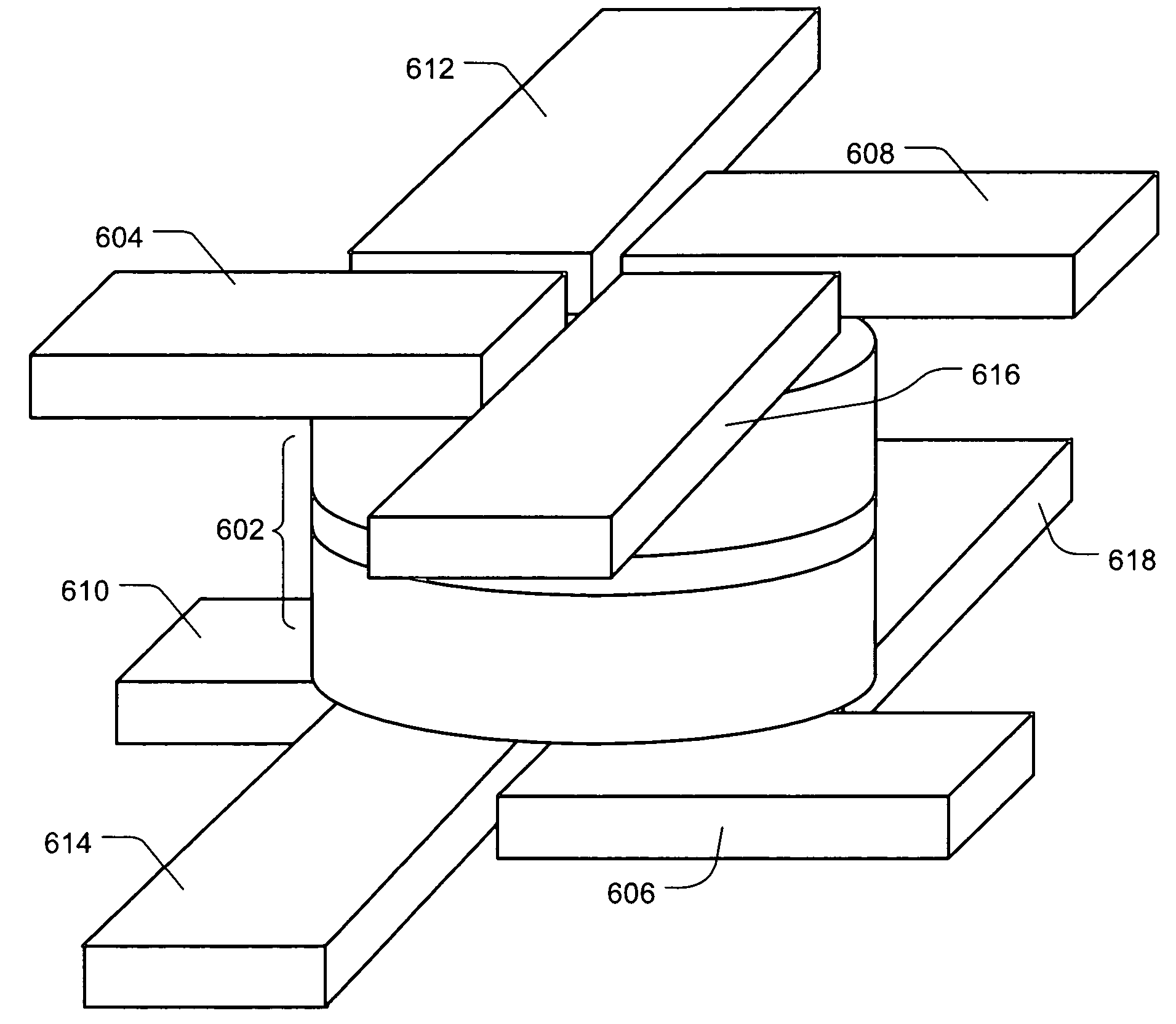
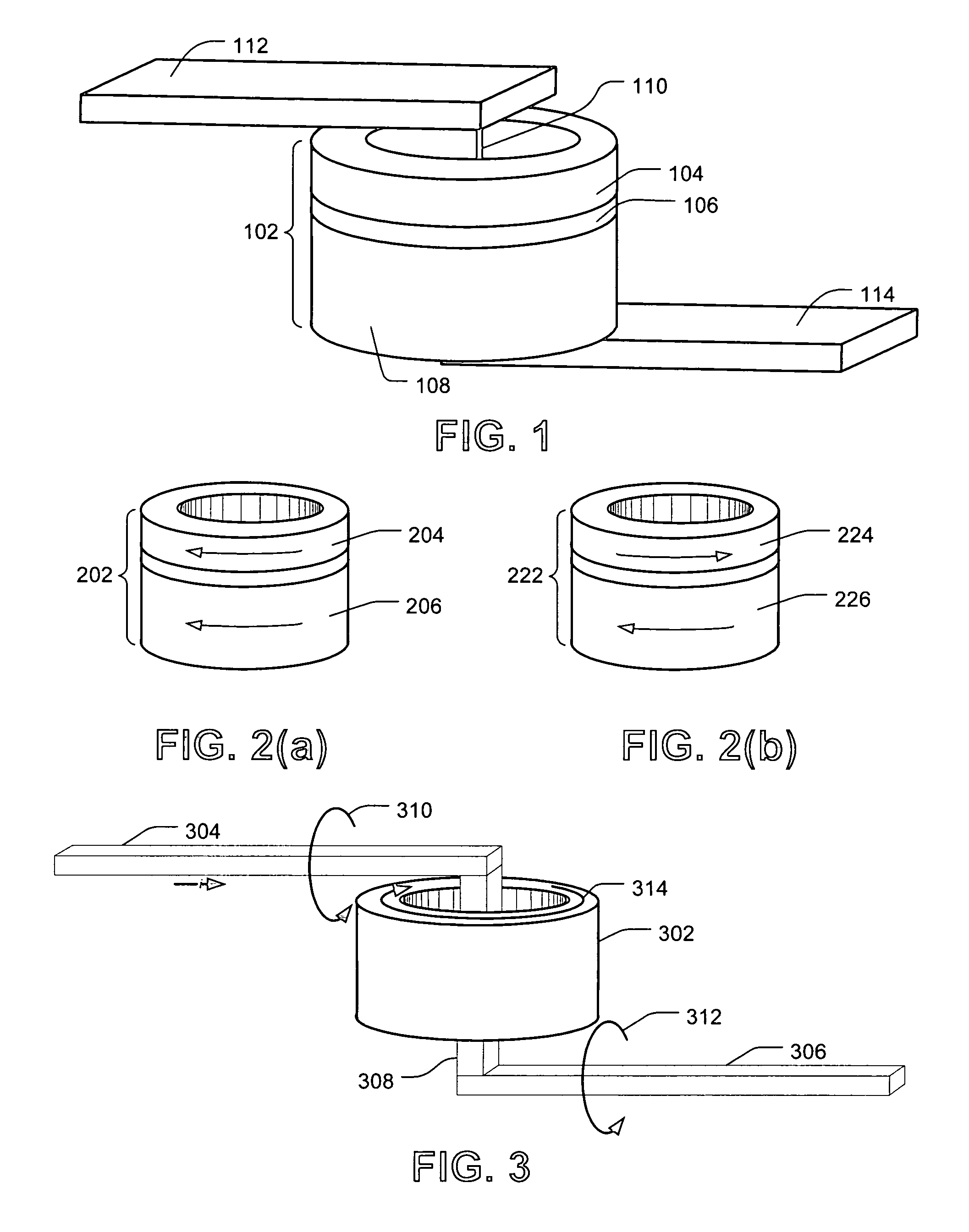
[0031]In an exemplary embodiment, a memory cell has a ring-shaped magnetoresistive element (or bit) configured with a word line threaded through a center hole in the ring-shaped element. FIG. 1 provides a perspective view of a simplified memory cell. A ring-shaped multilayer magnetoresistive element 102 is shown having three ring layers stacked vertically. Two ferromagnetic ring layers, 104 and 108, sandwich a nonmagnetic spacer layer 106 (typically copper for GMR or alumina Al2O3 for MTJ). A via 110 is positioned within a center hole (or aperture) of the ring-shaped element 102 and extends vertically from the top of the element 102 to the base of the ring-shaped element 102. A top write-read line 112 is coupled with the top of the via 110. The top write-read line 112 extends radially from the center hole past the curved perimeter of the ring-shaped element 102. Likewise, a base write-read line 114 is coupled with the base of the via 110. The top write-read line 114 exten...


PUM


Abstract

A magnetoresistive memory cell and array are provided for nonvolatile storage of binary information. According to an embodiment, a memory cell has a ring-shaped magnetoresistive multilayer element (or bit). A plurality of vias pass through a center hole in the ring-shaped element. Each end of each via is coupled with a separate write-read line segment that extends radially from the center hole past a perimeter of the ring-shaped element. The write-read lines are configured to generate magnetic fields for switching a magnetization direction of one or more layers of the ring-shaped bits in the array.

Description

GOVERNMENT RIGHTS[0001]The United States Government has acquired certain rights in this invention pursuant to Contract No. N00030-02-C-0006 awarded by the Strategic Projects Branch of the Navy.BACKGROUND[0002]1. Field[0003]The present invention relates generally to magnetic memory and more specifically to magnetoresistive memory elements.[0004]2. Background and Related Art[0005]In magnetoresistive random access memory (MRAM), data is stored by using an electric current to create a magnetic field for switching a magnetic direction of a ferromagnetic layer of a multilayer memory element (also known as a bit). An MRAM is described as a type of nonvolatile memory because a logical state of a memory element will persist even when power is removed from the memory device. Although there are other types of nonvolatile memory chips, MRAM allows rapid read and write sequences. And unlike dynamic random access memory (DRAM), MRAM does not require a constant flow of current to retain its data—t...

Claims


Application Information

Patent Timeline
Patent Type & Authority Patents(United States)
IPC IPC(8): G11C11/00
CPCG11C11/155
Inventor SUNDSTROM, LANCE
Owner HONEYWELL INT INC
Why Eureka
Try Eureka