Exercise device

a technology of exercise device and ellipse, which is applied in the field of exercise equipment and, can solve the problems of reducing the ratio of the major axis to the minor axis of the ellipse, not being optimal for biomechanics, and the nature of the ellipse, and achieves the effect of storing or moving more efficiently

a technology of exercise device and ellipse, which is applied in the field of exercise equipment and, can solve the problems of reducing the ratio of the major axis to the minor axis of the ellipse, not being optimal for biomechanics, and the nature of the ellipse, and achieves the effect of storing or moving more efficiently

US7060005B2Inactive Publication Date: 2006-06-13CONGRESS FINANCIAL CORP WESTERN

Image

  • Exercise device
  • Exercise device
  • Exercise device

Examples


Embodiment Construction

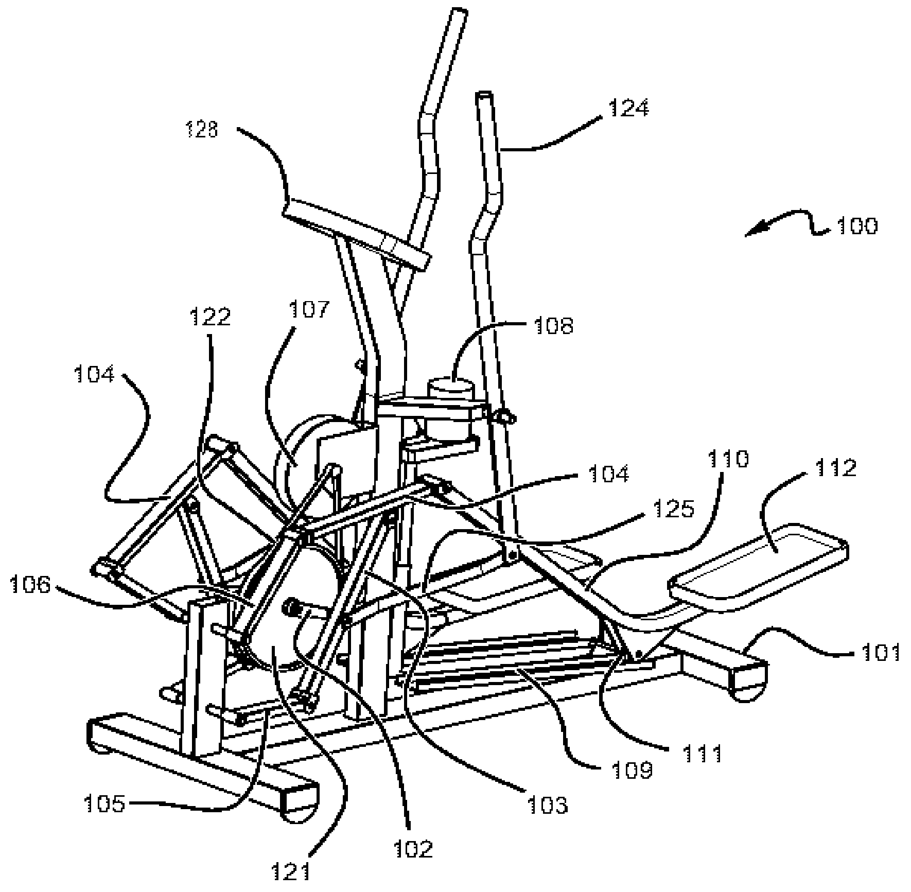
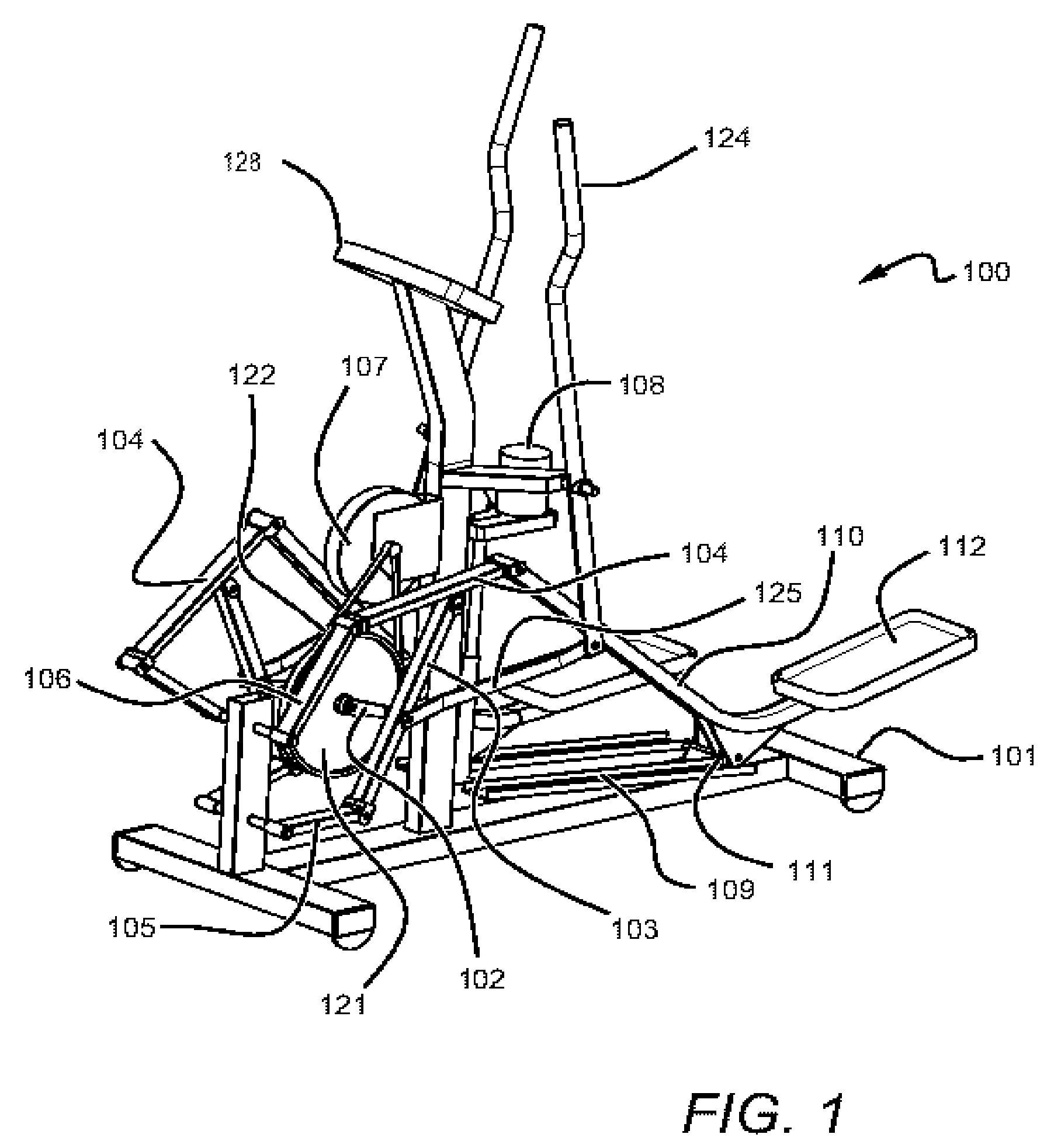
[0039]A preferred embodiment exercise machine constructed according to the principles of the current invention is designated as 100 inFIGS. 1 and 2.

[0040]Exercise machine 100 comprises a frame 101 that is intended to rest on a floor or other supporting surface. Frame 101 includes a crank axis which is essentially perpendicular to the longitudinal axis of frame 101 and a pair of cranks 102, both rotatably connected to frame 101 at the crank axis.

[0041]Exercise machine 100 includes a generally symmetrical layout of left and right hand linkage elements mounted on frame 101. Generally speaking, the motion of the linkage elements, link and convert a relatively complex closed path traveled by left and right pedals 112 to a simple circular motion of the crank arms 102.

[0042]The linkage assembly is comprised of left and right pedal arms 110, left and right intermediate links 104, left and right output links 103, rocker links 105 and 106.

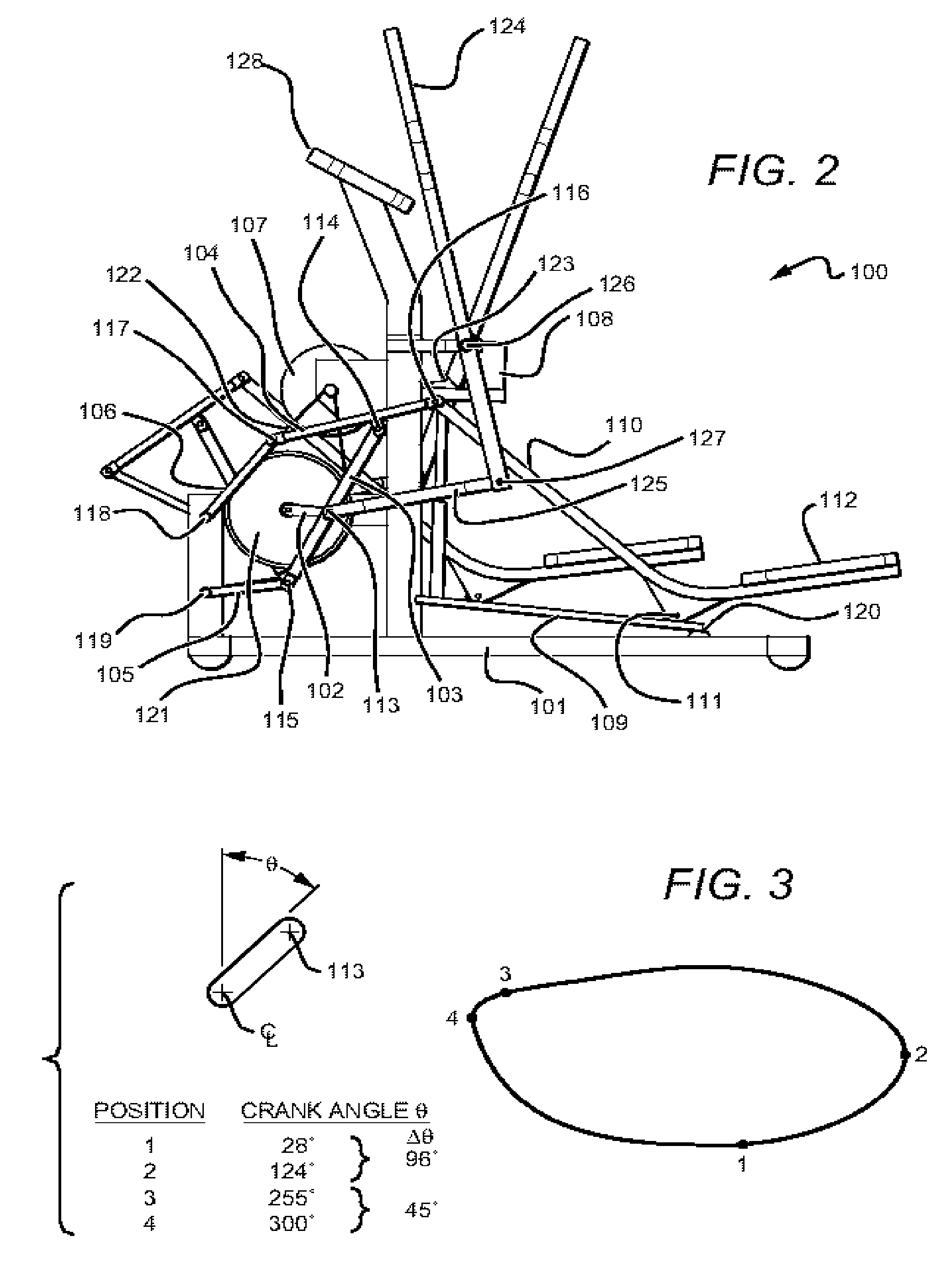
[0043]Viewing FIG. 2, left and right output links 103 ...


PUM


Abstract

An exercise apparatus having a pair of support pedals that, when a user steps upon both pedals, can be moved by the user in a closed path that is designed to be complimentary in motion to that of the user's natural stride. The pedals are operably connected by a linkage that facilitates this natural motion. Moreover, this linkage can be adjusted thereby altering the shape of the closed path traveled by the pedals. The closed path can thus be altered to conform to the optimal biomechanics of each individual user or, it can be altered to form a closed path designed for more of a striding type of exercise or for more of a climbing exercise, thereby allowing different muscle groups to be exercised on the same machine.

Description

CROSS-REFERENCE TO RELATED APPLICATIONS[0001]This application claims the benefit of U.S. Provisional Application bearing Ser. No. 60 / 534,335 filed Jan. 5, 2004.FIELD OF THE INVENTION[0002]The present invention relates to exercise apparatus and methods to enhance exercise. More particularly, the present invention relates to exercise devices with closed curvilinear pedal paths which may be adjustable and may include coordinated arm motion.BACKGROUND OF THE INVENTION[0003]The benefits of regular exercise are well known and recently there has been considerable evolution in exercise products which are resistive in nature and designed to improve one's cardiopulmonary endurance. Initially, exercise bikes were developed which gave the user a plain circular pedal path that mimicked road cycling. Cross country ski machines have provided linear reciprocating paths. Steppers have mimicked the motion of climbing stairs with oscillatory pedals. Lately, there has been a trend toward more complicat...

Claims


Application Information

Patent Timeline
13 Jun 2006
Publication
US7060005B2
IPC
A63B69/16; A63B22/04; A63B22/00; A63B23/035; A63B23/04
CPC
A63B22/001; A63B22/0015; A63B22/0664; A63B2022/0676; A63B22/203; A63B2022/002; A63B2022/067; A63B22/201
Inventors
CARLSEN, STEVEN; LIU-MILLER, ANITA