Low profile compact vertical polarization antenna with reconfigurable directional pattern

A technology of vertically polarized antennas and directional diagrams, applied to antennas, resonant antennas, antenna grounding devices, etc., can solve the problems of large antenna size, low antenna space utilization, and unfavorable antenna installation and use

Inactive Publication Date: 2019-03-19
CHONGQING UNIV
View PDF4 Cites 9 Cited by
  • Summary
  • Abstract
  • Description
  • Claims
  • Application Information

AI Technical Summary

Problems solved by technology

However, in many previous studies, most reconfigurable vertically polarized antennas use a monopole antenna unit placed in the middle of the antenna as the excitation oscillator, and several parasitic monopole units are surrounded around the antenna. By using such as a PIN tube, the variable Capacitance tube and other active devices are controlled, and some parasitic monopoles and excitation oscillators are selected to form a Yagi antenna to form an end-fire beam to realize the reconfigurable antenna pattern. When the antenna works in a certain end-fire state, there is always The parasitic monopole is in an idle state, which undoubtedly leads to low utilization of the antenna space, resulting in a large antenna size, which is not conducive to the installation and use of the antenna

Method used


Image

  • Low profile compact vertical polarization antenna with reconfigurable directional pattern
  • Low profile compact vertical polarization antenna with reconfigurable directional pattern
  • Low profile compact vertical polarization antenna with reconfigurable directional pattern

Examples


Embodiment Construction

[0024] Preferred embodiments of the present invention will be described in detail below with reference to the accompanying drawings.

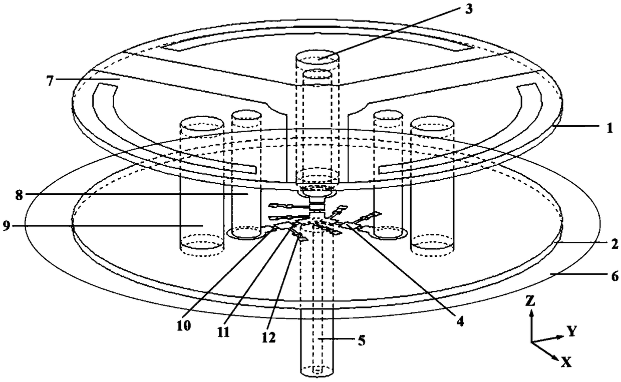
[0025] figure 1 It is a three-dimensional view of the overall structure of the low-profile compact vertically polarized antenna whose pattern can be reconfigured according to the present invention, such as figure 1 As shown, the antenna includes an upper dielectric substrate (1), a lower dielectric substrate (2), three identical top-loaded folded monopoles (3), a feed structure (4), a coaxial cable (5) and Large floors (6).

[0026] Such as figure 1 As shown, the upper dielectric substrate (1) and the lower dielectric substrate (2) are placed in parallel and separated from each other, and the lower dielectric substrate (2) is located directly below the upper dielectric substrate (1). Both dielectric substrates are Taconic RF-35, the relative permittivity is 3.5, the loss tangent is 0.0018, the substrate radius is 24mm, the thickness is 0.76m...


PUM

PropertyMeasurementUnit
Thicknessaaaaaaaaaa
Widthaaaaaaaaaa
Lengthaaaaaaaaaa

Abstract

The invention relates to a low profile compact vertical polarization antenna with a reconfigurable directional pattern, and belongs to the field of antenna design. The antenna comprises an upper dielectric substrate, a lower dielectric substrate, three identical top loaded folded monopoles, a feed structure, a coaxial cable and a metal floor. According to the invention, top loaded patches are rationally designed into the shape of a fan, so that the patches can be integrated on the same dielectric substrate to reduce the antenna size; then a curved groove is etched on each fan-shaped patch to further reduce the size of a monopole unit; and finally, three PIN switching diodes are skillfully utilized, so that the monopoles are alternately used as excitation oscillators and parasitic oscillators, and the directional pattern of the antenna can be reconstructed. The alternate working mode greatly reduces the antenna size. According to the invention, the designed vertical polarization antennahas three reconfigurable directional pattern modes, can realize 360-degree scanning in the horizontal direction, and has the advantages of low profile and compact structure.

Description

technical field [0001] The invention belongs to the technical field of antennas, and relates to a low-profile compact vertically polarized antenna with a reconfigurable pattern. Background technique [0002] On the one hand, the pattern reconfigurable vertically polarized antenna has great advantages in improving signal-to-noise ratio, reducing multipath effects, and saving energy; on the other hand, compared with horizontal The polarization method is not easy to generate polarization current, thus avoiding a large attenuation of energy and ensuring the effective transmission of signals. Therefore, vertically polarized antennas with reconfigurable pattern have received extensive attention in recent years. However, in many previous studies, most reconfigurable vertically polarized antennas use a monopole antenna unit placed in the middle of the antenna as the excitation oscillator, and several parasitic monopole units are surrounded around the antenna. By using such as a PIN...

Claims


Application Information

Patent Timeline
IPC IPC(8): H01Q1/38H01Q1/48H01Q9/30H01Q1/50H01Q19/10H01Q3/00
CPCH01Q1/38H01Q1/48H01Q1/50H01Q3/00H01Q9/30H01Q19/10
Inventor 唐明春段云露武震天陈晓明李梅李道通熊汉理查德.齐奥尔科夫斯基
Owner CHONGQING UNIV
Why Eureka
Try Eureka