Adjustable floating plate lumber support

a floating plate and support technology, applied in the field of seats, can solve the problems of high cost, complex construction, and substantial time and cost for fabrication and installation, and achieve the effect of easy integration into the seat structur

Active Publication Date: 2006-08-01
ALFMEIER CORPORATIO
View PDF15 Cites 38 Cited by
  • Summary
  • Abstract
  • Description
  • Claims
  • Application Information

AI Technical Summary

Benefits of technology

[0010]An adjustable lumbar support mechanism, constructed in accordance with the present invention, is provided which provides advantages over the prior art. The adjustable lumbar support can be easily integrated into a seat structure. The adjustable lumbar support includes a floating plate that “self centers” or “self aligns” offering firm yet compliant support and that “moves” with the occupant and is fully sprung, so as not to interfere with state of the art vibration insulation aspects of a seat, especially a vehicle seat. The floating support plate includes a curved front surface used to achieve lumbar support for a seat. The floating support plate is supported by a support linkage which includes first and second spring members that are engaged, either directly or indirectly, with the seat frame. The degree of lumbar support is adjusted by altering the effective length of the support linkage. A manual adjustment is provided for as well as a power adjustment. The powered embodiment is fully adaptable with “memory seating”, wherein the memory function is provided by means of hall effect pulse, counting of motor rotations or simple potentiometer based sensors as is readily known to those skilled in the art.

Problems solved by technology

Both of the devices described in the '643 and '348 patents are of complex construction and require substantial time and cost for fabrication and installation.
The requirements for the installation of a mounting plate, as well as the inter-securement of the bladder and plate elements, are primary reasons for the high cost, complexity of construction and the need of substantial time for the manufacture and installation of each device.
This device proved to be complicated and costly to manufacture.

Method used


Image

  • Adjustable floating plate lumber support
  • Adjustable floating plate lumber support
  • Adjustable floating plate lumber support

Examples


Embodiment Construction

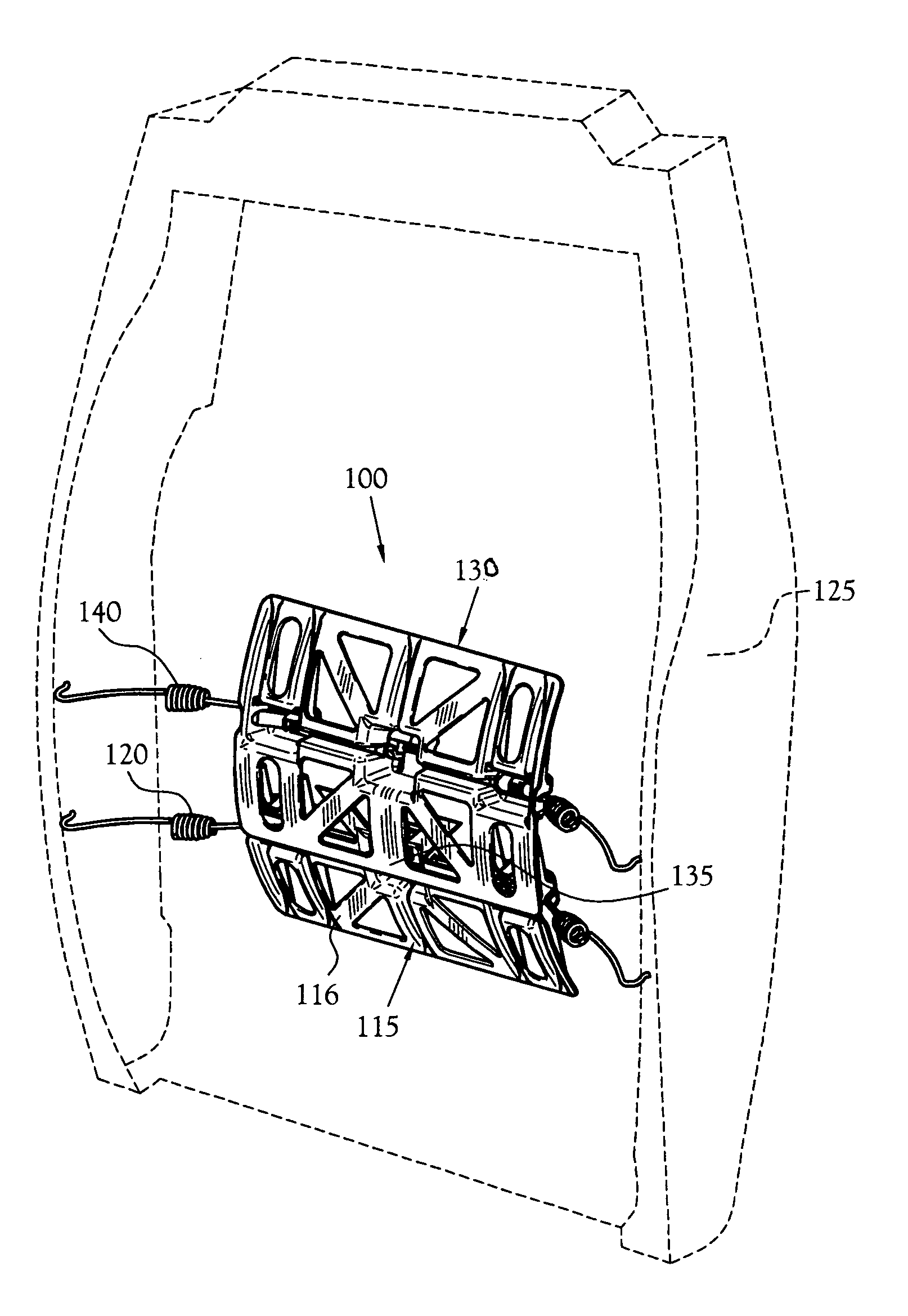
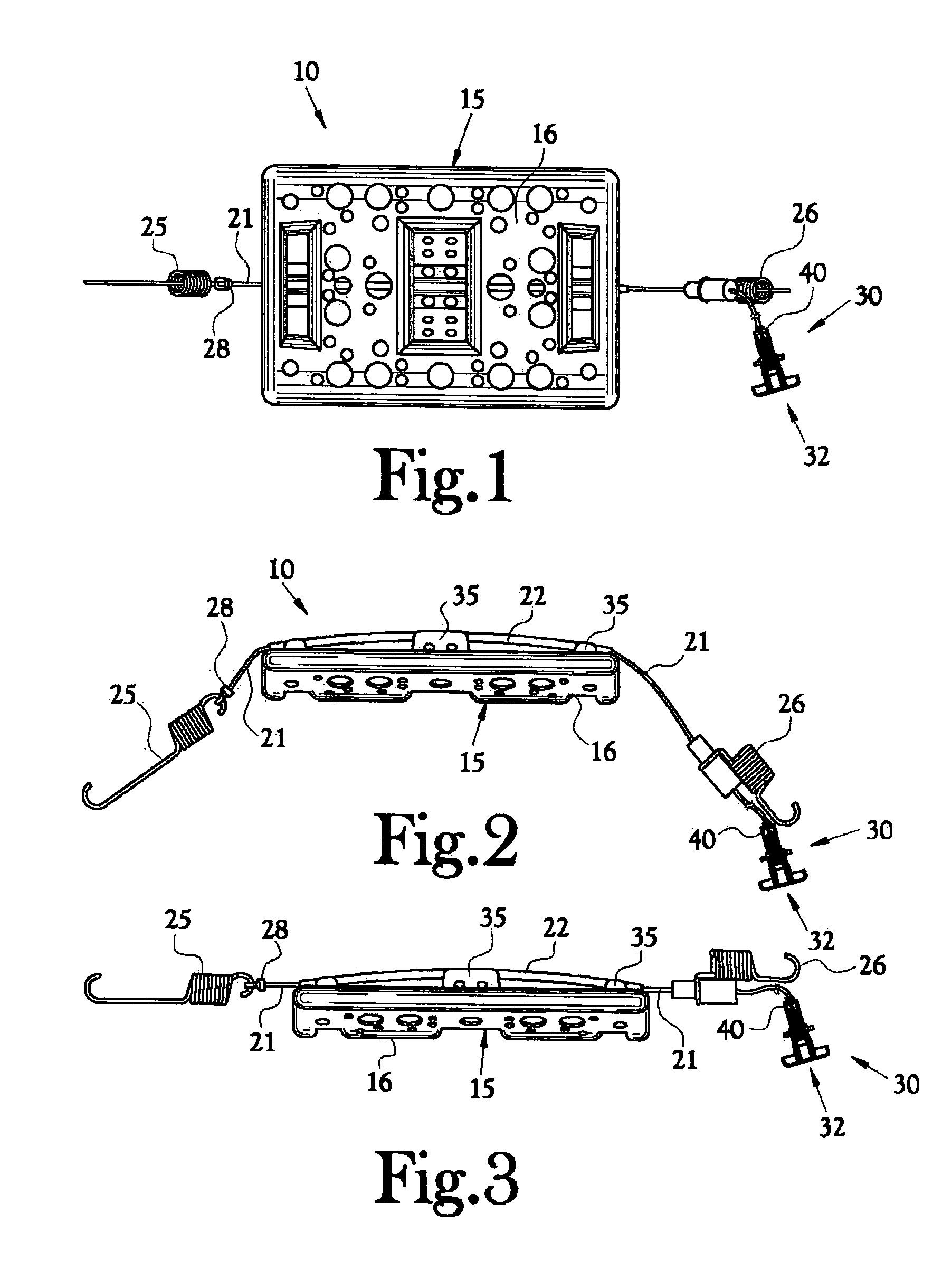
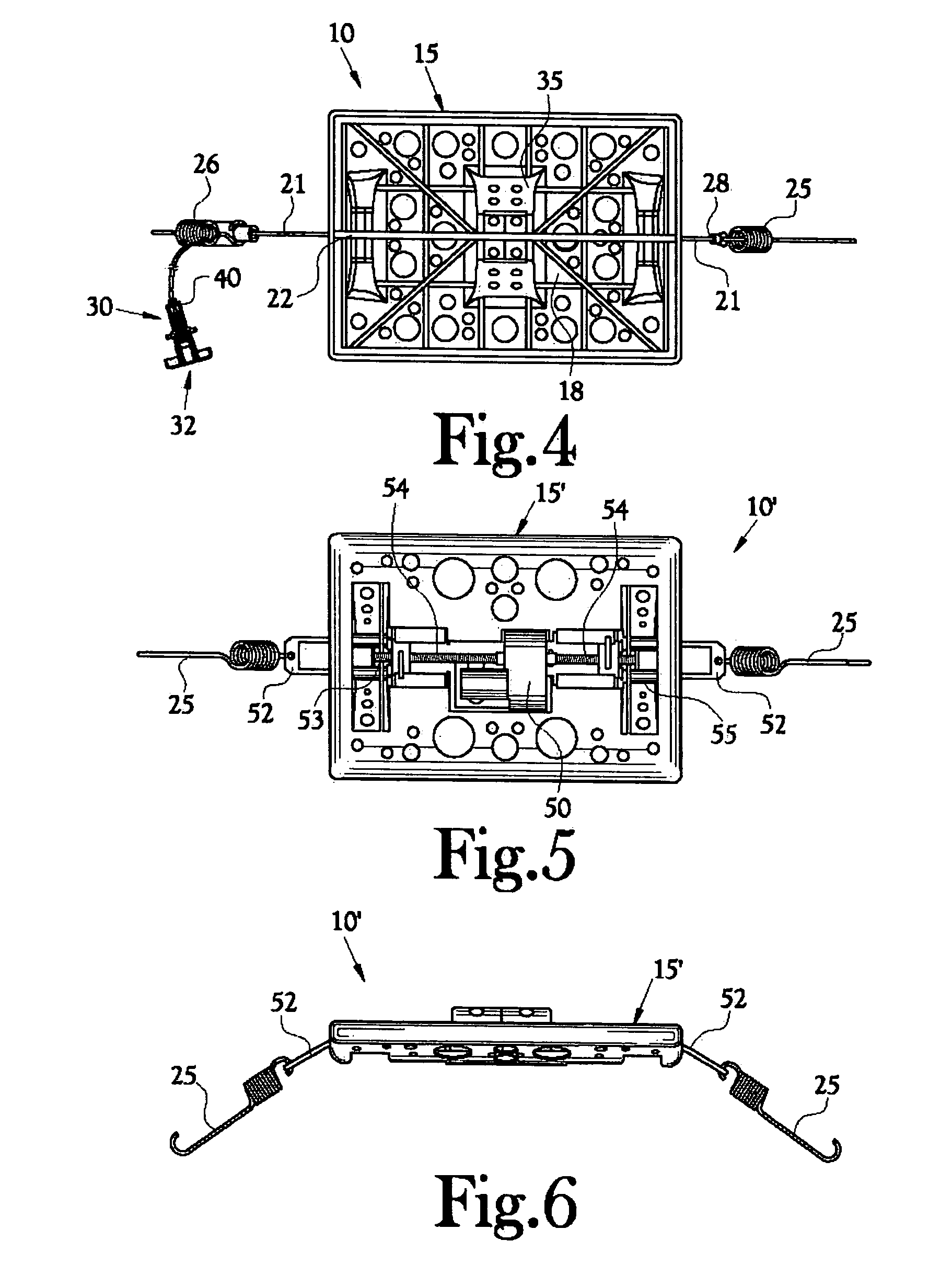
[0026]An adjustable lumbar support mechanism, constructed in accordance with the present invention, is illustrated generally as 10 in the figures. The adjustable lumbar support 10 provides a lumbar support mechanism which is adapted to be easily integrated into new or existing seat structures with minimal efforts and minimal costs. Moreover, in the preferred embodiment, the adjustable lumbar support 10 enables discrete regulation of the degree seat support provided to an individual's lumbar spine area and, thereby, maximizes the individual's comfort while occupying a seat. The lumbar support 10 includes a floating plate that “self centers” or “self aligns” offering firm yet compliant support and that “moves” with the occupant and is fully sprung, so as not to interfere with state of the art vibration insulation aspects of a seat, especially a vehicle seat.

[0027]FIGS. 1–4 illustrate one configuration of a floating support plate 15 having a curved front surface 16 used to achieve lumb...


PUM


Abstract

An adjustable lumbar support (100) adapted to be easily integrated into new or existing seat structures. Adjustable lumbar support (100) includes a lower floating plate (115) that is adapted to have a second, or upper, plate (130) hinged relative to the lower plate (115). The upper and lower plates have independently actuated support linkages (120 and 140) that are selectively actuated by first and second actuating mechanisms. In this manner, selective actuation actuator mechanisms associated with the lower and upper support plates (115 and 130) provides adjustment of a vertical dimension of the adjustable floating plate lumbar support. The degree of support provided by floating plates (115 and 130) is adjusted by adjusting the effective length of the support linkages.

Description

CROSS-REFERENCE TO RELATED APPLICATIONS[0001]This application claims the benefit of U.S. Provisional Application No. 60 / 378,854 filed May 8, 2002, PCT Application PCT / US02 / 022440 filed on Jul. 11, 2002 and to PCT Application PCT / US03 / 14258 filed on May 7, 2003.STATEMENT REGARDING FEDERALLY SPONSORED RESEARCH OR DEVELOPMENT[0002]Not ApplicableBACKGROUND OF THE INVENTION[0003]1. Field of Invention[0004]The present invention relates generally to seats, including vehicular seats. More particularly, the present invention relates to an adjustable lumbar support for a seat.[0005]2. Description of the Related Art[0006]It is well-recognized that a person sitting in a seat for an extended time period may desire additional support to obtain greater seat comfort and / or alleviate seat discomfort. Vehicle operators, vehicle passengers, and people whose jobs require them to be seated for extended periods of time are typically chief among those individuals who seek such additional support. The supp...

Claims


Application Information

Patent Timeline
Patent Type & Authority Patents(United States)
IPC IPC(8): A47C31/00B60N2/66
CPCB60N2/66B60N2/666B60N2/6671B60N2/6673
Inventor MASSARA, ANDREW J.VOGT, BRANDON R.
Owner ALFMEIER CORPORATIO
Why Eureka
Try Eureka