Unlock instant, AI-driven research and patent intelligence for your innovation.

Image display apparatus, image display method and computer-readable recording medium storing image display program

a display apparatus and image technology, applied in the direction of picture reproducers using projection devices, instruments, color signal processing circuits, etc., can solve the problems of deterioration of the rgb ratio (balance) of the projected image, narrow brightness range (dynamic range) that can be displayed, and difficult improvement of image quality, so as to achieve simple correction calculation, the effect of dynamic range of the displayed image and the ability to change the dynamic rang

Inactive Publication Date: 2006-08-08
SEIKO EPSON CORP
View PDF19 Cites 18 Cited by
  • Summary
  • Abstract
  • Description
  • Claims
  • Application Information

AI Technical Summary

Benefits of technology

[0013]Because the image display apparatus and image display method of the first aspect transform expanded image signals of a plurality of primary colors into color space that includes chromaticity and lightness, and, after correcting the chromaticity, then transforms the color space back into image signals of a plurality of primary colors, the dynamic range of a displayed image can be altered without changing the ratios of the image signals of the plurality of primary colors.
[0031]By employing this structure, because the correction device is able to take the flux of leakage light also into consideration when making a correction, it is able to correct chromaticity more correctly.

Problems solved by technology

In this projection type of liquid crystal display, liquid crystal light valves are used as an imager, however, due to leakage light and stray light, the brightness range (dynamic range) that can be displayed is narrow, and in some cases an improvement in image quality is difficult to achieve.
However, if an image displayed on a light valve is expanded, problems occur such as the RGB ratio (balance) of a projected image deteriorating, and the color (i.e., the vividness of the color) of the projected image changing.

Method used


Image

  • Image display apparatus, image display method and computer-readable recording medium storing image display program
  • Image display apparatus, image display method and computer-readable recording medium storing image display program
  • Image display apparatus, image display method and computer-readable recording medium storing image display program

Examples


first embodiment

[0073]FIG. 2 is a block diagram showing the structure of a drive circuit of the projection type display apparatus of the

[0074]Firstly, image signals are input into an image processing section 21 and an image analysis section 24. In the image analysis section 24, the image signals are analyzed and an expansion coefficient is calculated. This is then supplied to the image processing section 21 as an image control signal.

[0075]The image analysis section 24 also controls an optical modulator driver 25 based on optical modulation control signals. The optical modulator driver 25 controls the optical modulator 26. The optical modulator driver 25 changes the quantity of illumination light from the light source 510 in accordance with whether or not there is an image signal expansion supplied to the respective light valves 522, 523, and 524 by the image processing section 21. As a result, it is possible to achieve smooth gradation expression while enlarging the brightness range of a displayed...

second embodiment

[0177]FIG. 8 is a block diagram showing the structure of a drive circuit of the projection type display apparatus of the

[0178]In the drive circuit of the second embodiment, expansion coefficients and offset values (offset quantity) are supplied from the image analysis section 24 to the image processing section 21. The term “offset values” refers to the darkest value among the image data. By subtracting the offset value from the image signal when performing offset processing, unnecessary black floating can be suppressed in an image signal.

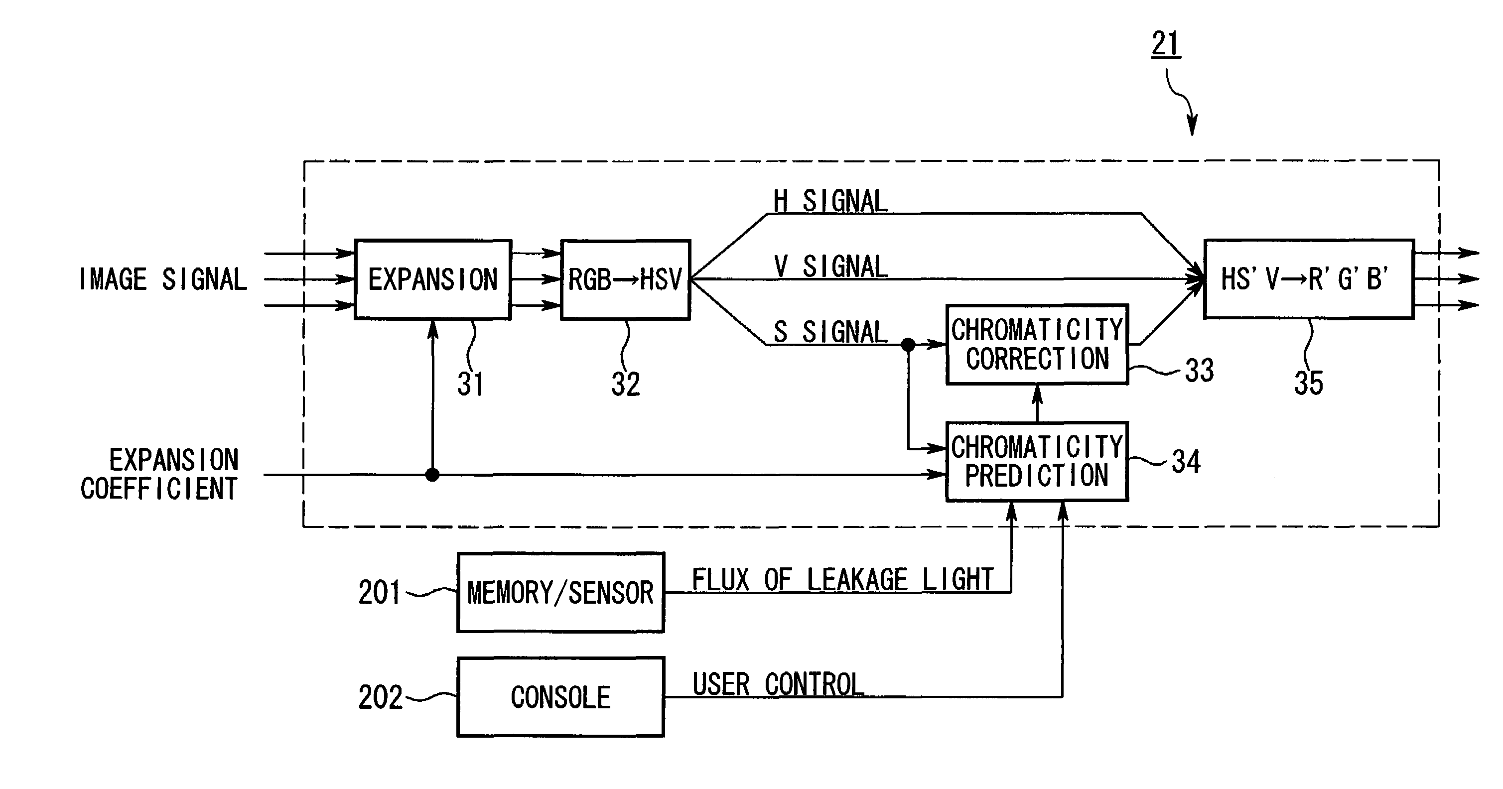
[0179]FIG. 9 is a block diagram showing the structure of the image processing section 21 of the second embodiment when transforming image signals into HSV space. Note that the same numbers are given to component elements that are identical to those of the image processing section of FIG. 3, and a description thereof is omitted.

[0180]As is shown in FIG. 9, the image processing section 21 is provided with an offset processing section 36, an expansion ...

third embodiment

[0273]FIG. 13 is a block diagram showing the structure of the image processing section 21 of the The image processing section 21 is provided with calculation sections 370, 371, and 372 that make color corrections of R signals, G signals, and B signals.

[0274]The image processing section 21 of the third embodiment makes color corrections of the respective RGB colors by direct calculation using the calculation sections 370, 371, and 372 without performing color space transformation on the image signals such as is described in the first and second embodiments.

[0275]Here, the calculation formula employed by the calculation sections 370, 371, and 372 of the image processing section 21 of the third embodiment will be described. As an example, a description is given of when the flux of leakage light is δv and the offset value is v0. The image on the screen are written (R0, G0, B0)=(r0+δv, g0+δv, b0+δv). The displayed image after 1 / p optical modulation and expansion by a factor of p can be ...


PUM

PropertyMeasurementUnit
brightnessaaaaaaaaaa
color spaceaaaaaaaaaa
coloraaaaaaaaaa

Abstract

An image display apparatus in which image signals of a plurality of primary colors are transformed by an image processing section into color space that includes lightness and chromaticity. When the chromaticity (color vividness) in this color space is being corrected, the correction method is changed in accordance with the optical modulation state of the display apparatus. If optical modulation is performed, then correction is made to lower the chromaticity, while correction is made to raise the chromaticity when there is no optical modulation.

Description

BACKGROUND OF THE INVENTION[0001]1. Field of the Invention[0002]The present invention relates to an image display apparatus, an image display method, and a computer readable recording medium storing an image display program.[0003]2. Description of Related Art[0004]In recent years, the performance required by various fields in an image display apparatus has increased as informational technology has advanced. Among such image display apparatuses, a liquid crystal display that allows optical characteristics to be changed by the electrical control of the orientation of liquid crystal molecules, that has low power consumption, that is flat-panel shaped, and that does not strain the eyes and the like has become particularly sought after. Furthermore, a projection type of liquid crystal display (liquid crystal projector) in which images emitted from an optical system that uses liquid crystal light valves are transmitted through a projection lens and projected in enlargement on a screen is ...

Claims


Application Information

Patent Timeline
Patent Type & Authority Patents(United States)
IPC IPC(8): G09G5/02G02F1/133G09G3/20G09G3/36H04N9/30H04N9/31H04N9/64
CPCH04N9/3105H04N9/3197H04N9/3182H04N9/3155
Inventor YOSHIDA, SHOHEI
Owner SEIKO EPSON CORP