Demodulator, receiver, and communication system

a demodulator and receiver technology, applied in the field of demodulators, can solve the problem that the correcting capability of convolutional codes cannot be drawn out sufficiently, and achieve the effect of satisfying the bit error rate performan

Inactive Publication Date: 2006-09-05
MITSUBISHI ELECTRIC CORP
View PDF13 Cites 6 Cited by
  • Summary
  • Abstract
  • Description
  • Claims
  • Application Information

AI Technical Summary

Benefits of technology

[0026]It is an object of this invention to provide a demodulator which is capable of outputting soft decision data, and a receiver and a communication system having the

Problems solved by technology

However, in the conventional demodulator, since the multiple differential phase detector outputs the demodulated data according to the hard decision, namely, since an input into the Viterbi decoder

Method used


Image

  • Demodulator, receiver, and communication system
  • Demodulator, receiver, and communication system
  • Demodulator, receiver, and communication system

Examples


first embodiment

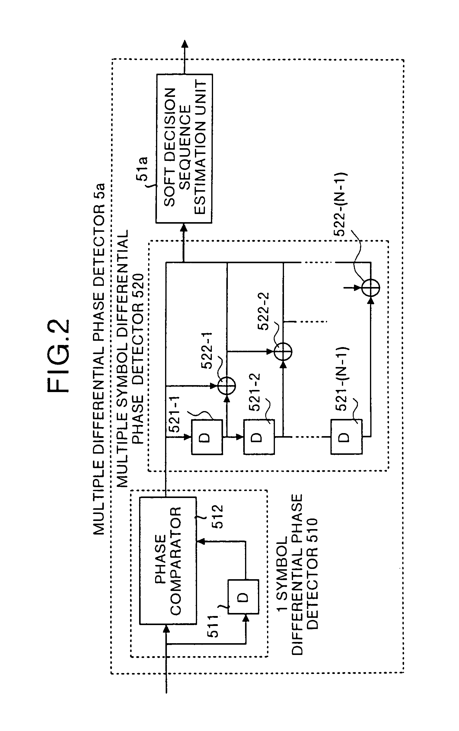
[0091]FIG. 6 is a diagram showing a structure of the multiple differential phase detector 5b which operates as a demodulator in the present embodiment. The same reference numerals are given to the parts of the structure which are the same as those of the multiple differential phase detector 5a (see FIG. 2) and the description thereof is omitted. The multiple differential phase detector 5b comprises a soft decision sequence estimation unit 51b, and a power detector 52 for detecting the power of the received signal.

[0092]Operation of the receiver will be explained here. Since the operation of the transmitter, the functions of the 1 symbol differential phase detector 510 and multiple symbol differential phase detector 520 are same as explained in connection with the first embodiment, description thereof is omitted.

[0093]For example, the soft decision sequence estimation unit 51b estimates transmitted convolutional-coded data according to the Viterbi algorithm using the trellis diagram...

second embodiment

[0102]Operation of the receiver will be explained here. Since the operation of the transmitter, the functions of the 1 symbol differential phase detector 510, multiple symbol differential phase detector 520 and power detector 52 are the same as those in the first or second embodiment, the description thereof is omitted.

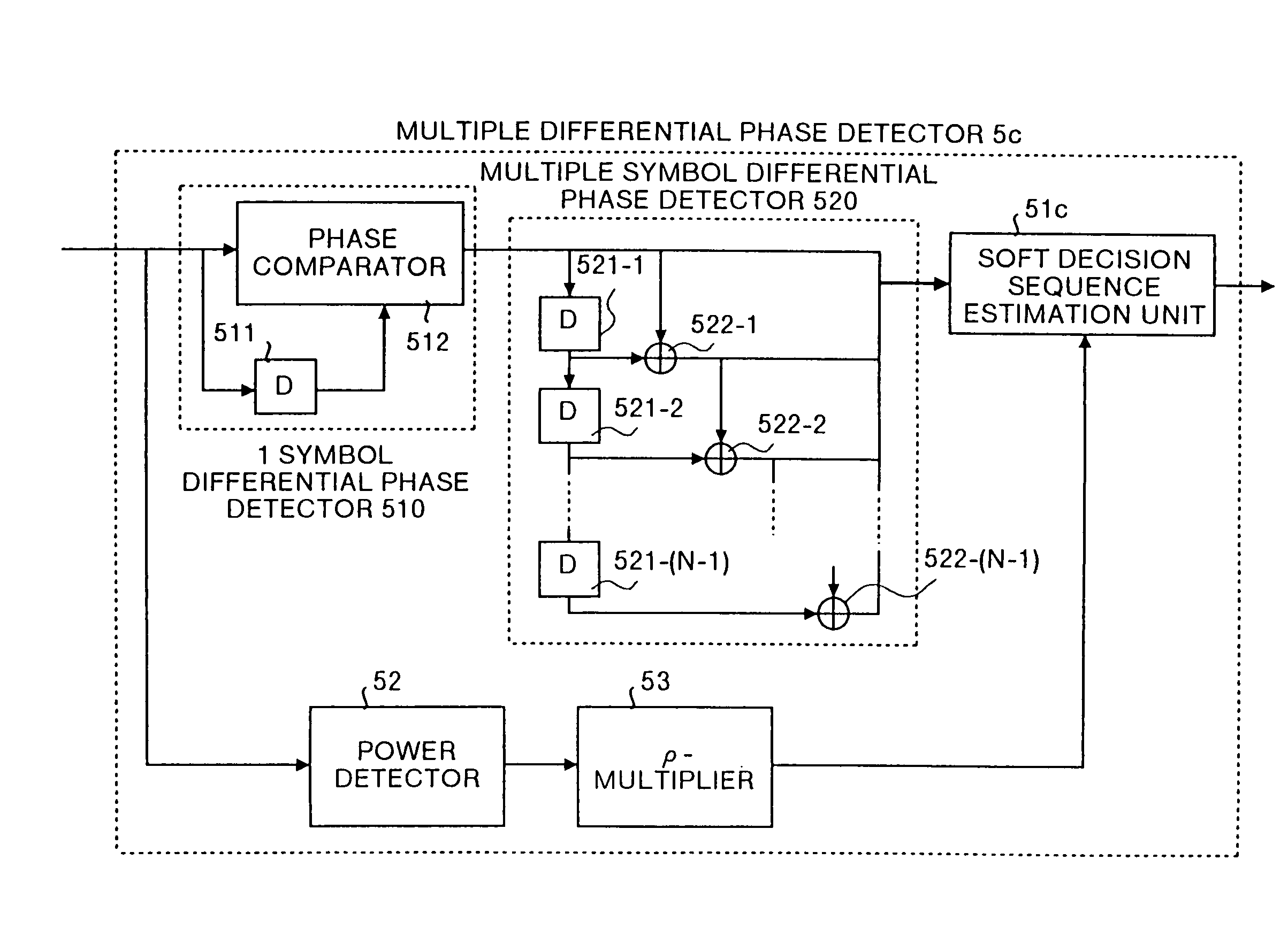
[0103]For example, the ρ-multiplier 53 multiples a power of a received signal output from the power detector 52 by ρ so as to output the calculated result. The soft decision sequence estimation unit 51c estimates transmitted convolutional-coded data according to the Viterbi algorithm using the trellis diagram showing transitions of phase states composed of combinations of (N−1) transmission differential phase signal points so as to output the estimated result as soft decision demodulated data. In the present embodiment, the convolutional-coded data are estimated according to a multiple symbol differential phase detect signal output from the multiple symbol differentia...


PUM


Abstract

A demodulator in a receiver has a multiple symbol differential phase detector which calculates phase differences between a received signal and received signals of 1, 2, . . . , N (Where N is an integer greater than 2) before so as to output the calculated results as N symbol differential phase detected signals. Further, a soft decision sequence estimating unit in this demodulator estimates a transmitted differential phase sequence according to the 1, 2, . . . , N symbol differential phase detected signals using a trellis diagram representing transitions of differential phase states of a transmitted signal and Viterbi algorithm and estimates soft decision demodulated data according to estimated transmitted differential phase sequence and the survival path metrics that transit into each state on the trellis diagram.

Description

FIELD OF THE INVENTION[0001]The present invention relates to a demodulator used for radio communication such as mobile communication and mobile satellite communication. More specifically, this invention relates to a demodulator using differential PSK (Phase Shift Keying) modulation and multiple differential phase detection. This invention also relates to a receiver and a communication system that make use of the demodulator of the present invention.BACKGROUND OF THE INVENTION[0002]First, a conventional demodulator will be explained. FIG. 10 is a diagram showing a structure of a prior demodulator (corresponding to a multiple differential phase detector 500) disclosed in “Differential Detection Scheme for DPSK using Phase Sequence Estimation” (Institute of Electronics, Information and Communication Engineers, Technical Report, RCS98-102, January, 1993).[0003]The conventional demodulator comprises, a multiple differential phase detector 500 for generating / outputting demodulated data fr...

Claims


Application Information

Patent Timeline
IPC IPC(8): H04L5/12H03D1/00H04L23/02H04L27/06H03M13/41H04L25/03H04L27/22H04L27/227H04L27/233
CPCH04L27/2332H04L25/03178
Inventor MATSUNAGA, MARIKOJIMA, TOSHIHARU
Owner MITSUBISHI ELECTRIC CORP
Why Eureka
Try Eureka