
Fastening means and process for its manufacture

a technology of fasteners and clips, applied in the field of fasteners, can solve the problems of relatively slow speed of the above described method of producing clip bars, and achieve the effect of increasing the production ra

Inactive Publication Date: 2006-09-12
JOH FRIEDRICH BEHRENS AG
View PDF15 Cites 1263 Cited by
  • Summary
  • Abstract
  • Description
  • Claims
  • Application Information

AI Technical Summary

Problems solved by technology

There are drawbacks to the above described approach.
First, the speed of the above described method of producing the clip bars is relatively slow, given that each single wires must be worked individually.

Method used


Image

  • Fastening means and process for its manufacture
  • Fastening means and process for its manufacture
  • Fastening means and process for its manufacture

Examples


example

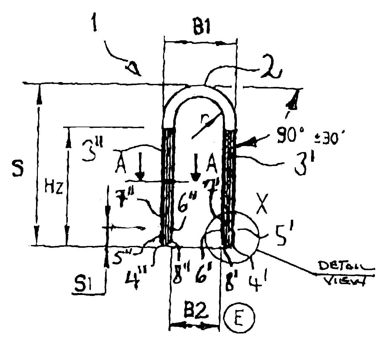
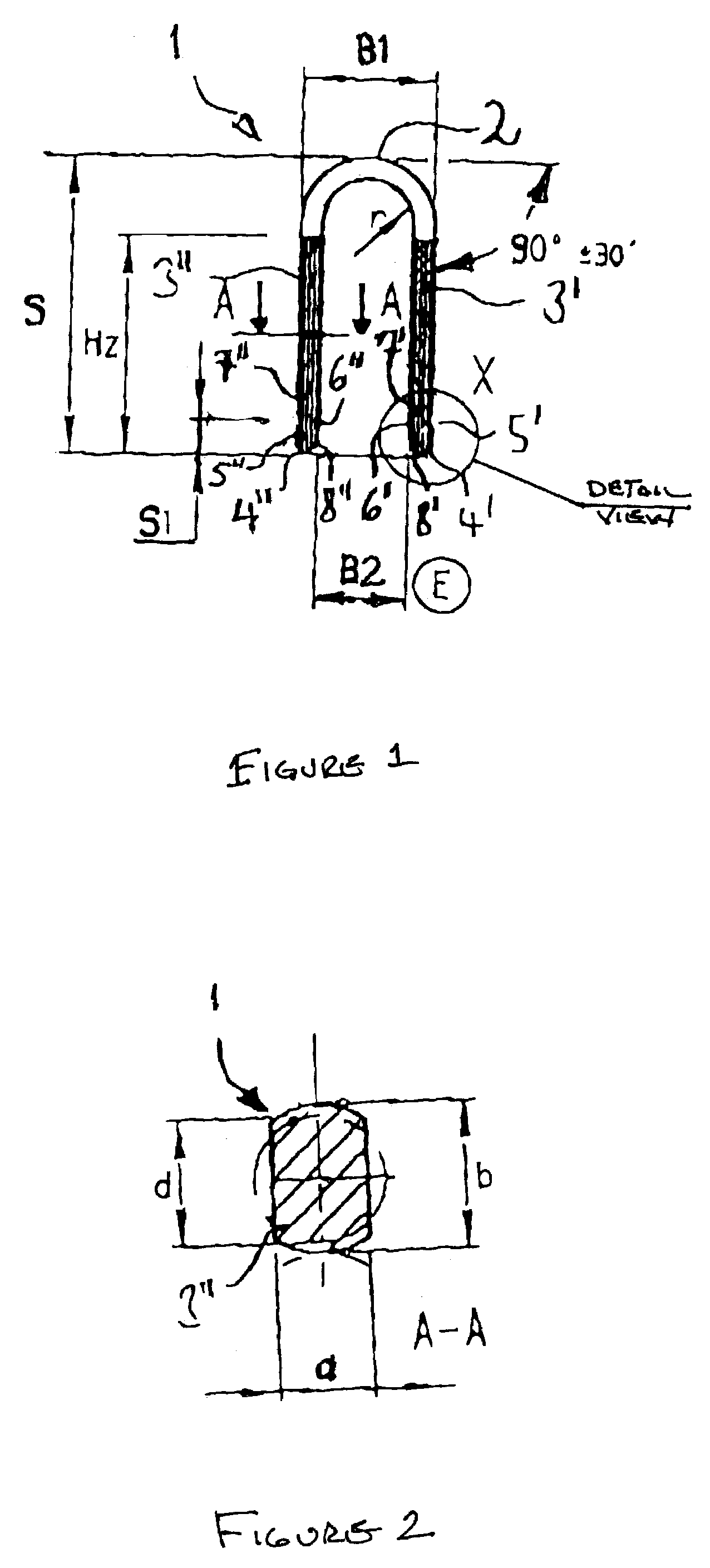
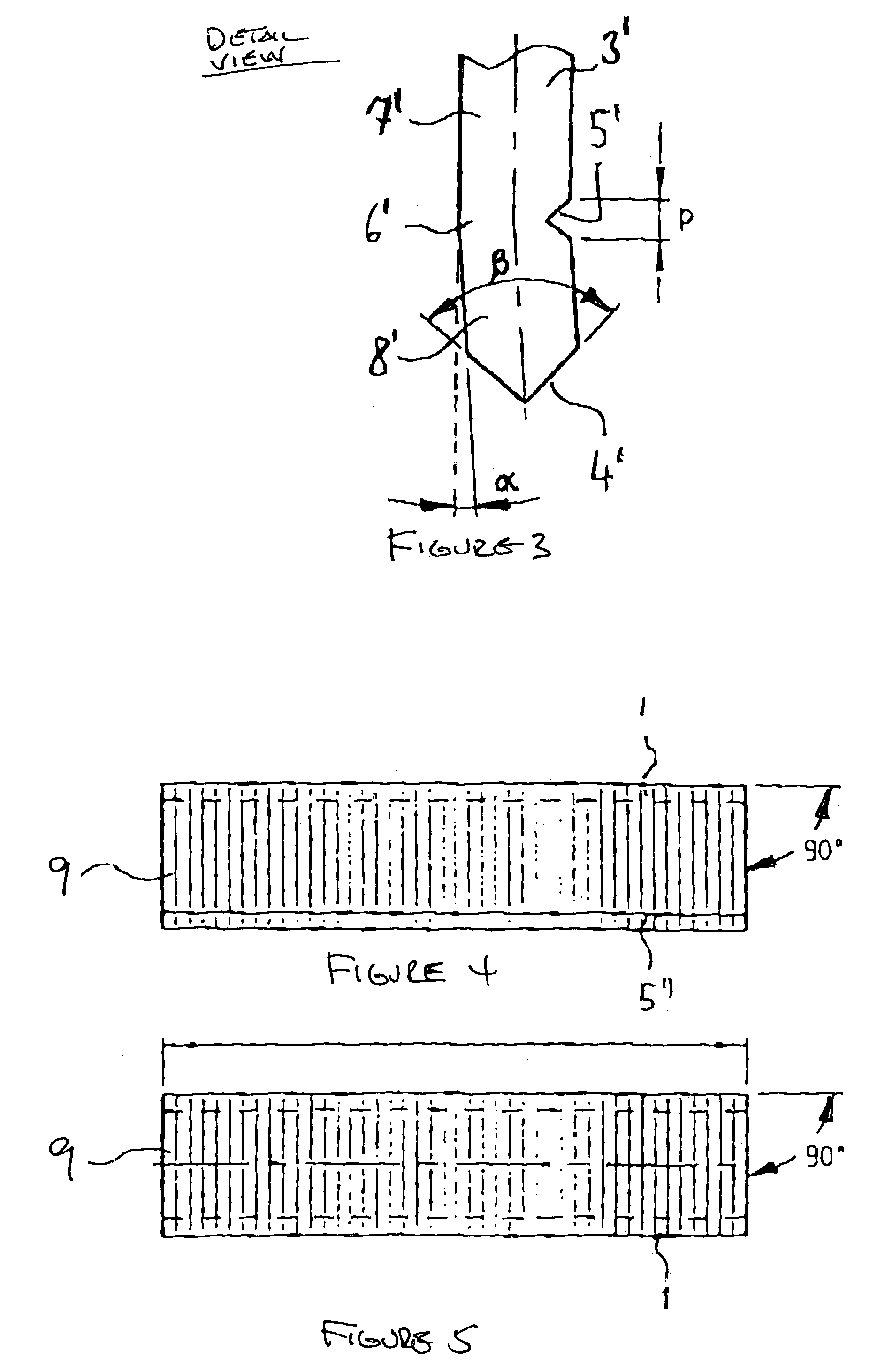
[0032]The invention will be further clarified by the following example which is intended to be exemplary of the invention. In one embodiment, the configuration depicted in FIGS. 1–3 is characterized by the following measurements:[0033]Thickness of the rolled wire a=1.44 mm[0034]Width of the rolled wire b=1.57 mm[0035]Bending radius r=3.225 mm[0036]Height of embossed point S1=2.5 mm[0037]Chiseled angle β=90°[0038]Bending angle of the angled portion α=1°[0039]Width of embossed point p=0.6 mm[0040]Height of clip S=19 mm[0041]External back width B1=9.3 mm[0042]Internal back width B2=6.45 mm

[0043]It is noted that angled portion α may have an angle between 1° to 7°. In another embodiment, angled portion α may have an angle between 3° to 5°. An angle of about 4° is particularly advantageous. Typically, the angled portion extends from the shank region having an irregularly reduced cross-section. This is particularly advantageous in producing the irregularly reduced cross-section and the ang...


PUM


Abstract

The present invention is directed to a fastener device that includes a base portion. At least one shank is coupled to the base portion. The at least one shank includes an end configured to be driven into a material. The at least one shank also includes a weakened shank region disposed between a first adjacent shank region and a second adjacent shank region. The weakened shank region includes a cross-section irregularly weakened with respect to the cross-sections of the first adjacent shank region and the second adjacent shank region.

Description

BACKGROUND OF THE INVENTION[0001]1. Field of the Invention[0002]The present invention relates generally to fasteners, and particularly to a clip fastener and a process for manufacturing the clip fastener.[0003]2. Technical Background[0004]Fastening clips and / or staples are typically made of a circular or flat wire bent to form a U-shape. In one approach that has been considered, the ends of the legs include a chisel-made chamfered cut. The chamfered cut enables the legs to penetrate the material into which the clips are driven with a straight run. In another approach that has been considered, clips have been made with an out-of-center saw-made chamfer cut at the ends of the legs. As a result, the legs of the clips will extend laterally from the original leg axis, thus increasing the pull-out resistance in many materials.[0005]The clips are manufactured with a saw-made chamfered cut by obliquely shearing off single wires at the ends across an edge, after which a multiplicity of singl...

Claims


Application Information

Patent Timeline
Patent Type & Authority Patents(United States)
IPC IPC(8): F16B15/00
CPCF16B15/0015Y10S411/92
Inventor KROHN, BURGHARDT
Owner JOH FRIEDRICH BEHRENS AG
Learn More