Flow cytometers and detection system of lesser size

a flow cytometer and detection system technology, applied in the field of flow cytometers, can solve the problems of failure, waste disposal, over-all size of the device, etc., and achieve the effects of maximizing the signal to noise ratio, reducing the number of particle parameters, and eliminating the complexity of the laser/photomultiplier detection system

Inactive Publication Date: 2006-09-12
RGT UNIV OF MICHIGAN
View PDF29 Cites 136 Cited by
  • Summary
  • Abstract
  • Description
  • Claims
  • Application Information

AI Technical Summary

Benefits of technology

[0009]It has now been surprisingly discovered that the focusing fluid of conventional flow cytometers can be replaced by a gas stream while maintaining substantially non-turbulent flow through an observation zone. It has been further surprisingly discovered that the complex, expensive, and bulky laser / photomultiplier detection system can be eliminated by relying on laser diodes in conjunction with PIN photodiodes for detection, preferably in conjunction with fiber optic light impingement and collection pathways. The latter system is capable of use with either gas-focusing or conventional liquid-focusing flow cytometers. Preferred flow cytometer cells are disposable, and can be configured for either gas or liquid focusing. Multi-directional light source and / or detection can be used to maximize signal to noise ratios and to increase the number of particle parameters which can be measured. Devices with geometries similar to gas-focusing flow cytometer cells but with hydrophilic surfaces may be used in applications where atomization of a fluid stream is desired.

Problems solved by technology

The necessity for a rather large volume of liquid relative to the volume of sample contributes to the overall size of the device, and with biological samples suspected of containing pathogens, contributes to waste disposal problems.
Reducing complexity by eliminating liquid focusing has been attempted, J. Crosland-Taylor, NATURE 171, 37–38 (1953), but has not been regarded as successful, due to deficiencies such as channel clogging and slow velocity of sample flow which reduces the optical detection rate.
0.07 m3) of space, and are quite expensive.
The optical components of the detection system are major contributors to the overall cost, as are the laser and photomultiplier.

Method used


Image

  • Flow cytometers and detection system of lesser size
  • Flow cytometers and detection system of lesser size
  • Flow cytometers and detection system of lesser size

Examples


Embodiment Construction

)

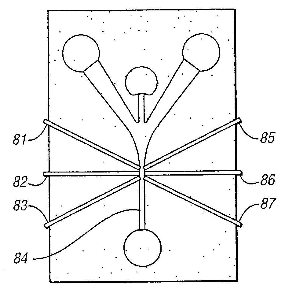
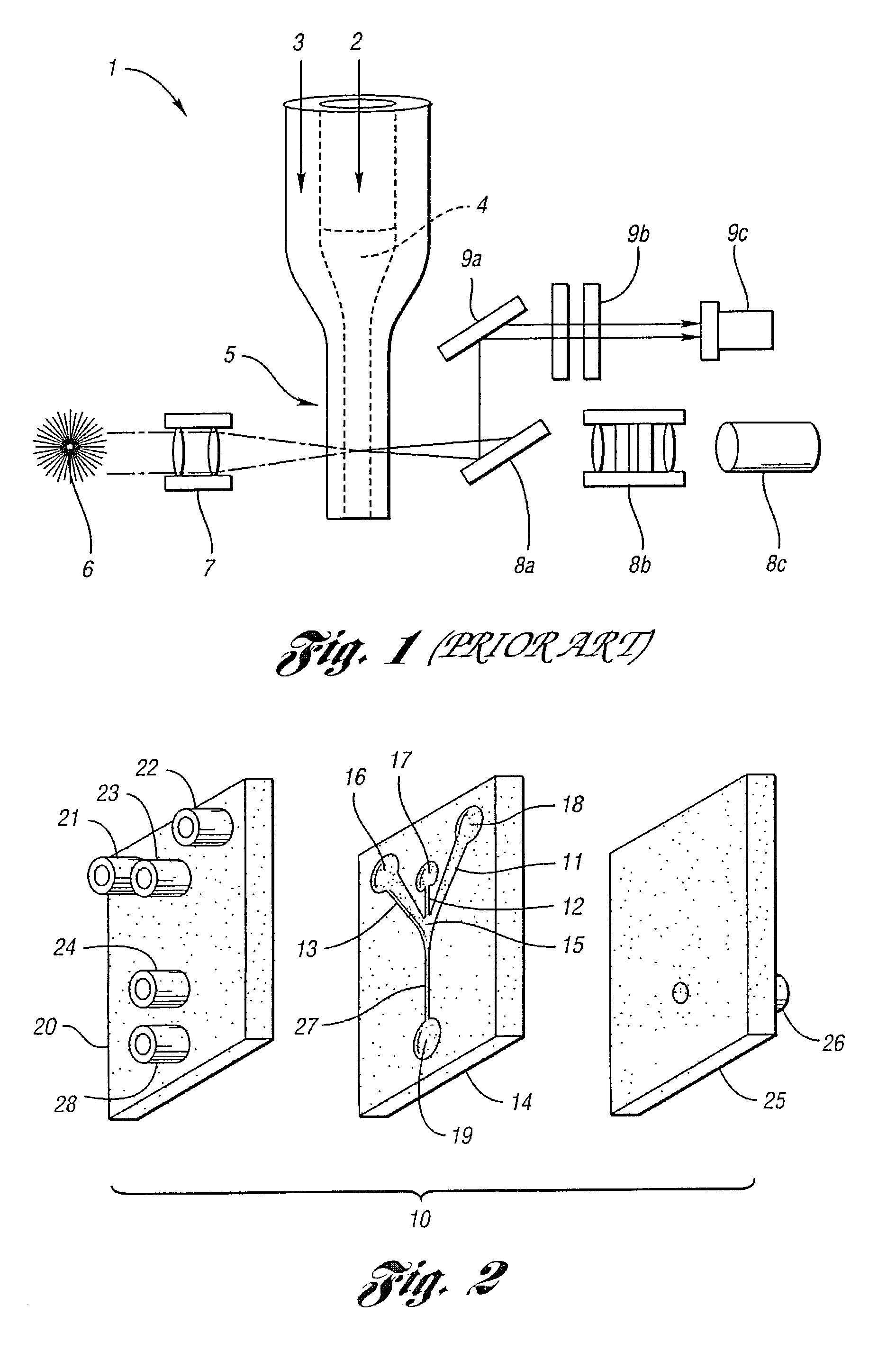
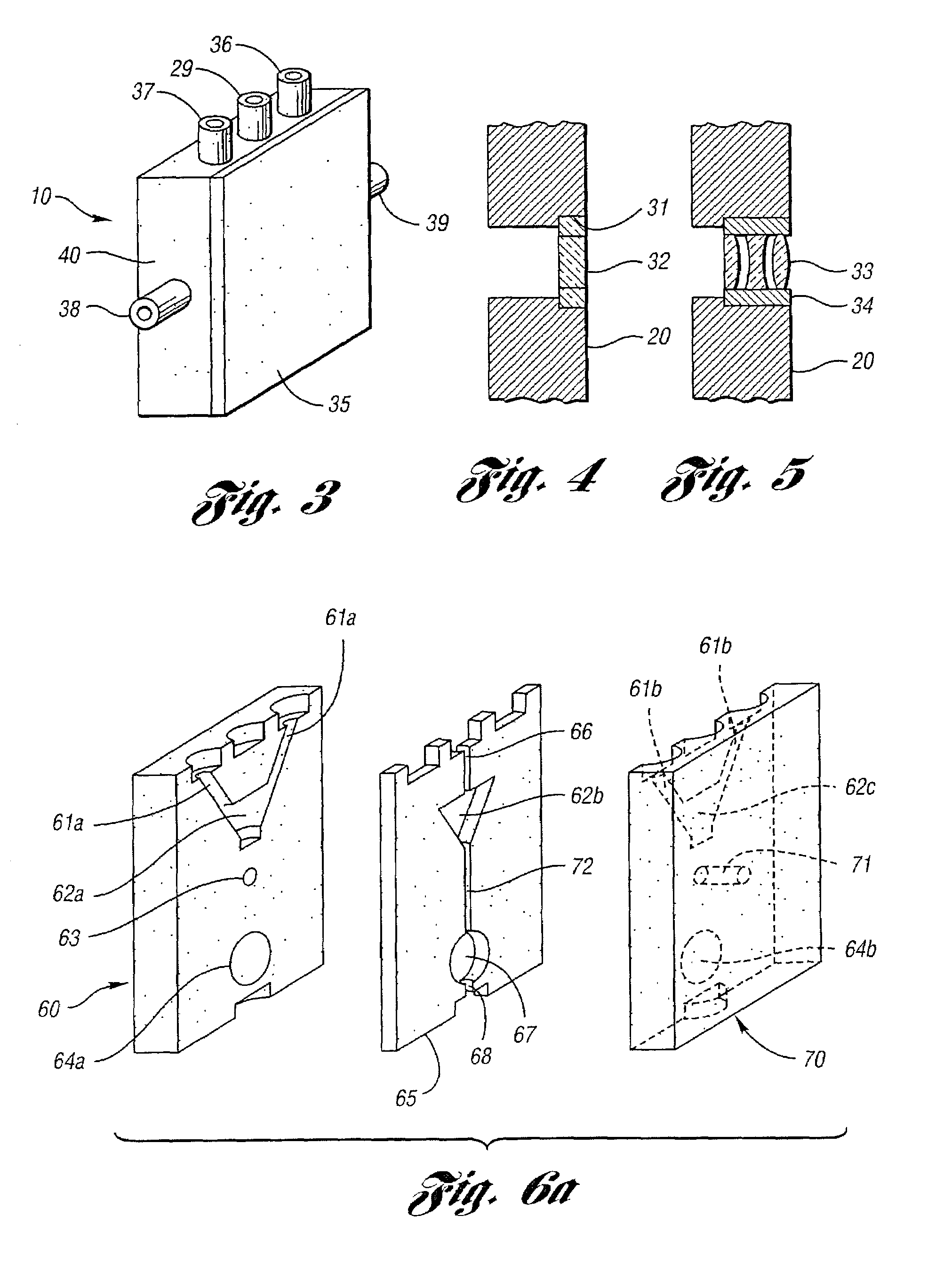
[0025]The flow cytometers of the present invention are best described in terms of conceptual components: a flow cell, a light source, a light impingement system, a light collection system, and a detector system. These components will be described separately, and may be configured in numerous permutations, as will be evident hereafter.

[0026]The flow cells and detection systems associated therewith may take the form of numerous embodiments. Thus, in one broad aspect, the subject invention pertains to flow cells which may be used to focus a liquid stream with the aid of at least one gas focusing stream. Such flow cells have numerous uses, of which flow cytometry is one example. The subject invention further pertains to novel detection systems usable with these and other flow cytometers, including liquid focusing flow cytometers.

[0027]In a further aspect of the invention, a detection system is provided which contains a light source comprising a plurality of laser diodes and / or LEDs whi...


PUM

PropertyMeasurementUnit
diameteraaaaaaaaaa
diameteraaaaaaaaaa
diameteraaaaaaaaaa

Abstract

Gas focusing flow cytometers are fabricatable employing simple and inexpensive manufacturing techniques. When such cytometers or conventional cytometers are combined with fiber optical light paths and laser diode and semiconductor photodetectors, light weight and handheld, optionally disposable devices which maintain high performance are possible.

Description

CROSS-REFERENCE TO RELATED APPLICATION[0001]This application claims the benefit of U.S. provisional application Ser. No. 60 / 306,382, filed Jul. 18, 2001.BACKGROUND OF THE INVENTION[0002]1. Field of the Invention[0003]The present invention is directed to flow cytometers.[0004]2. Description of the Related Art[0005]Flow cytometers are useful in the detection of particulates in liquid systems, in particular for the detection and / or identification of microbes, including pathogens. Flow cytometry per se is a mature technology. Flow cytometers concentrate a particulate-containing inlet stream to a relatively small diameter “observation” stream in which the particles pass “single file” past a detector located in an observation channel. Focusing of the liquid sample is achieved by injecting a liquid as a sheath surrounding the stream of sample. The necessity for a rather large volume of liquid relative to the volume of sample contributes to the overall size of the device, and with biologica...

Claims


Application Information

Patent Timeline
Patent Type & Authority Patents(United States)
IPC IPC(8): G01N21/03G01N21/63G01N15/10G01N15/14G01N33/49
CPCG01N15/1404G01N33/491G01N15/1484Y10T436/2575G01N2015/1413G01N2015/149G01N2015/1006
Inventor KURABAYASHI, KATSUOTAKAYAMA, SHUICHISKERLOS, STEVEN J.HUH, DONGEUNGROTBERG, JAMES B.TUNG, YI-CHUNG
Owner RGT UNIV OF MICHIGAN
Why Eureka
Try Eureka