Electrical ceiling box for fixture support

a technology for electrical boxes and ceiling fans, which is applied in the direction of machine supports, electrical apparatus casings/cabinets/drawers, coupling devices, etc., can solve the problems of difficult adaptation of the difficulty of adapting existing ceiling fan boxes for use with light fixtures or the lik

Active Publication Date: 2006-12-12
HUBBELL INC
View PDF22 Cites 78 Cited by
  • Summary
  • Abstract
  • Description
  • Claims
  • Application Information

AI Technical Summary

Problems solved by technology

Typically, a conventional electrical box used for supporting a light fixture or the like can not be used for supporting a ceiling fan.
Adapting existing light fixture boxes for use with ceiling fans is often quite difficult since light fixture boxes use smaller fasteners and are generally not strong enough to support fans without substantial reinforcements or special brackets.
Adapting existing ceiling fan boxes for use with a light fixture or the like is not always easily accomplished, since fasteners for the light fixture are different from the fasteners use with ceiling fans.
Moreover, fixture support fasteners often come in various colors, finishes and lengths as well as with various decorative features which may be difficult, if not impossible to match, in a fastener which can be used with an electrical box approved for use with ceiling fans.

Method used


Image

  • Electrical ceiling box for fixture support
  • Electrical ceiling box for fixture support
  • Electrical ceiling box for fixture support

Examples


Embodiment Construction

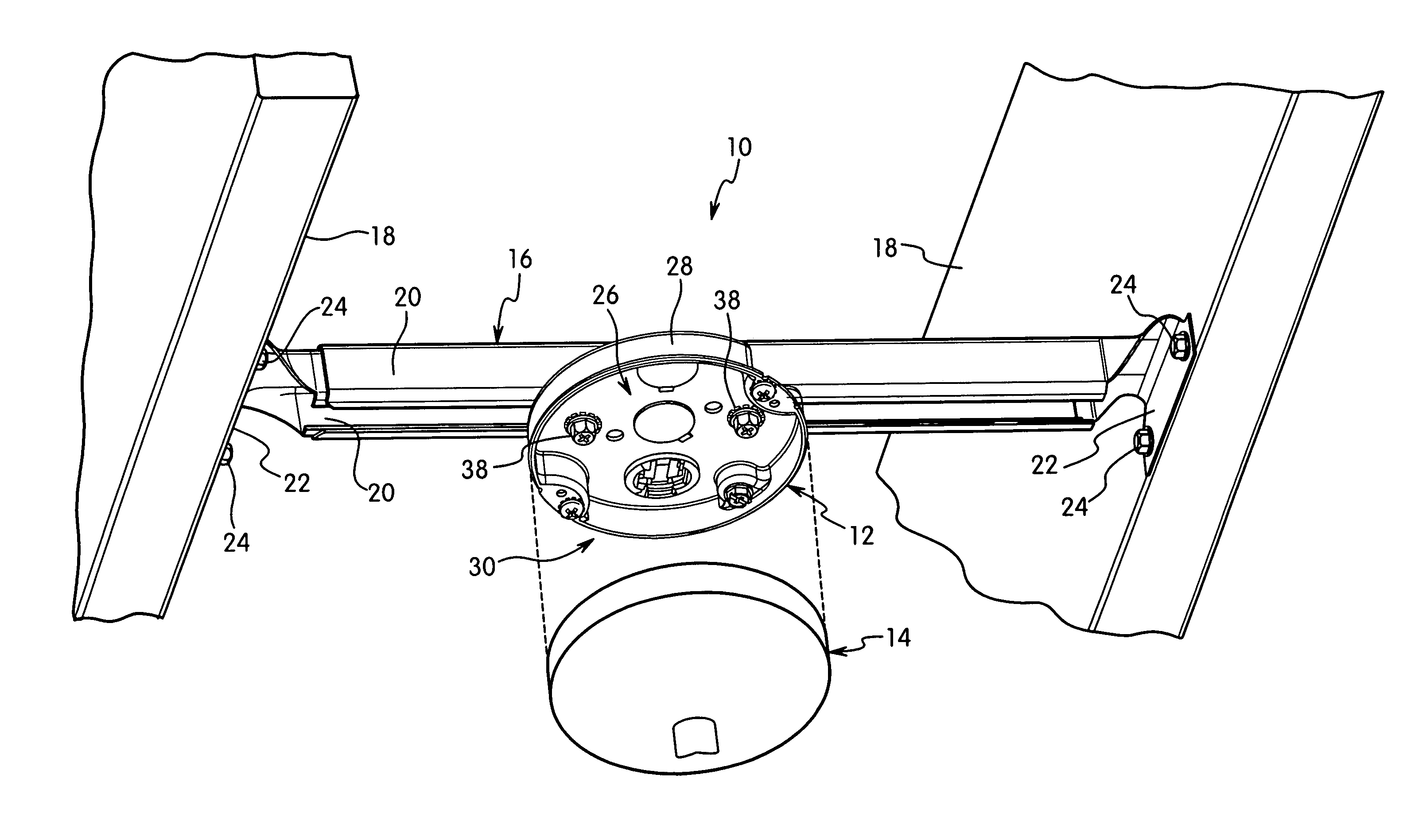
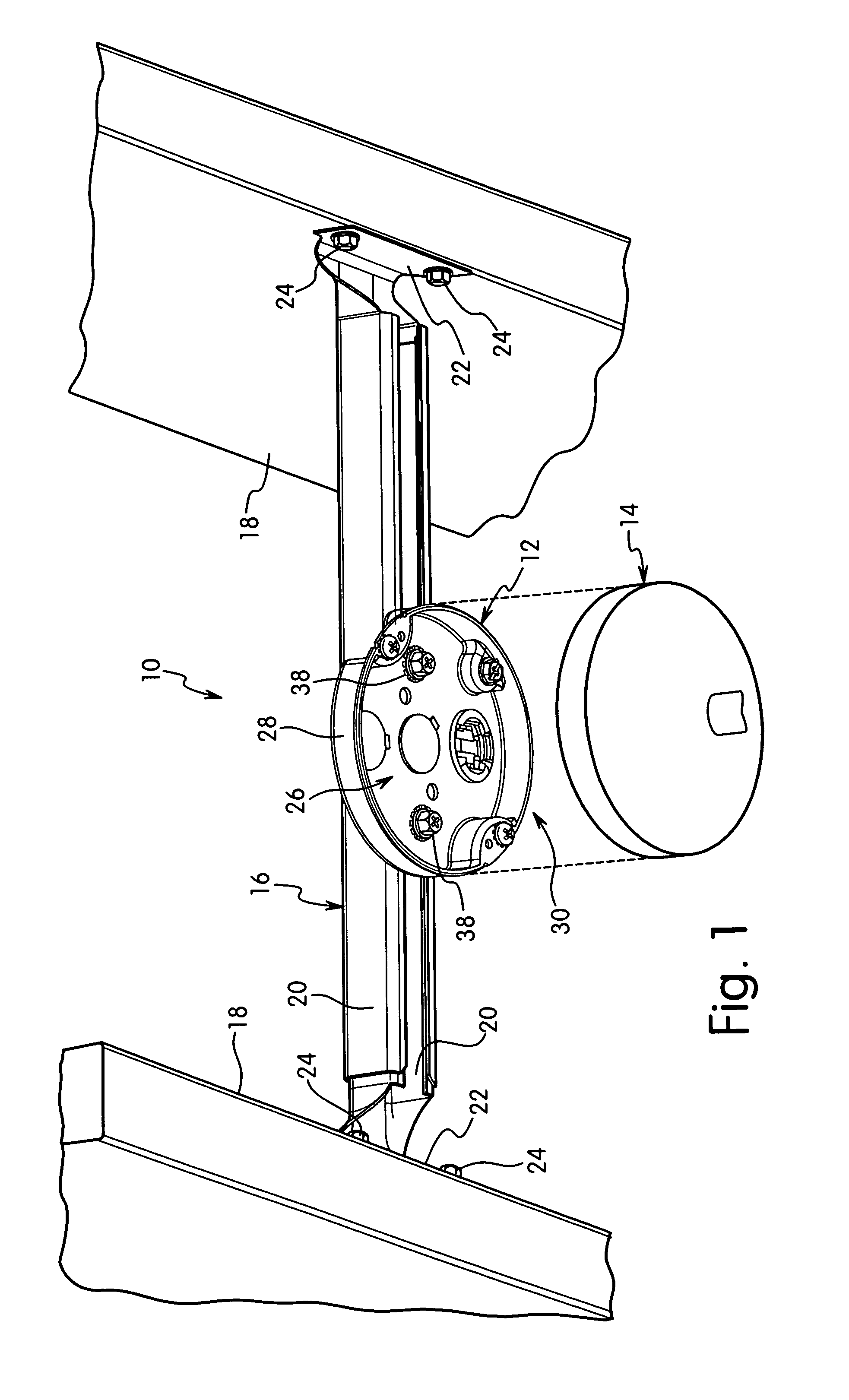
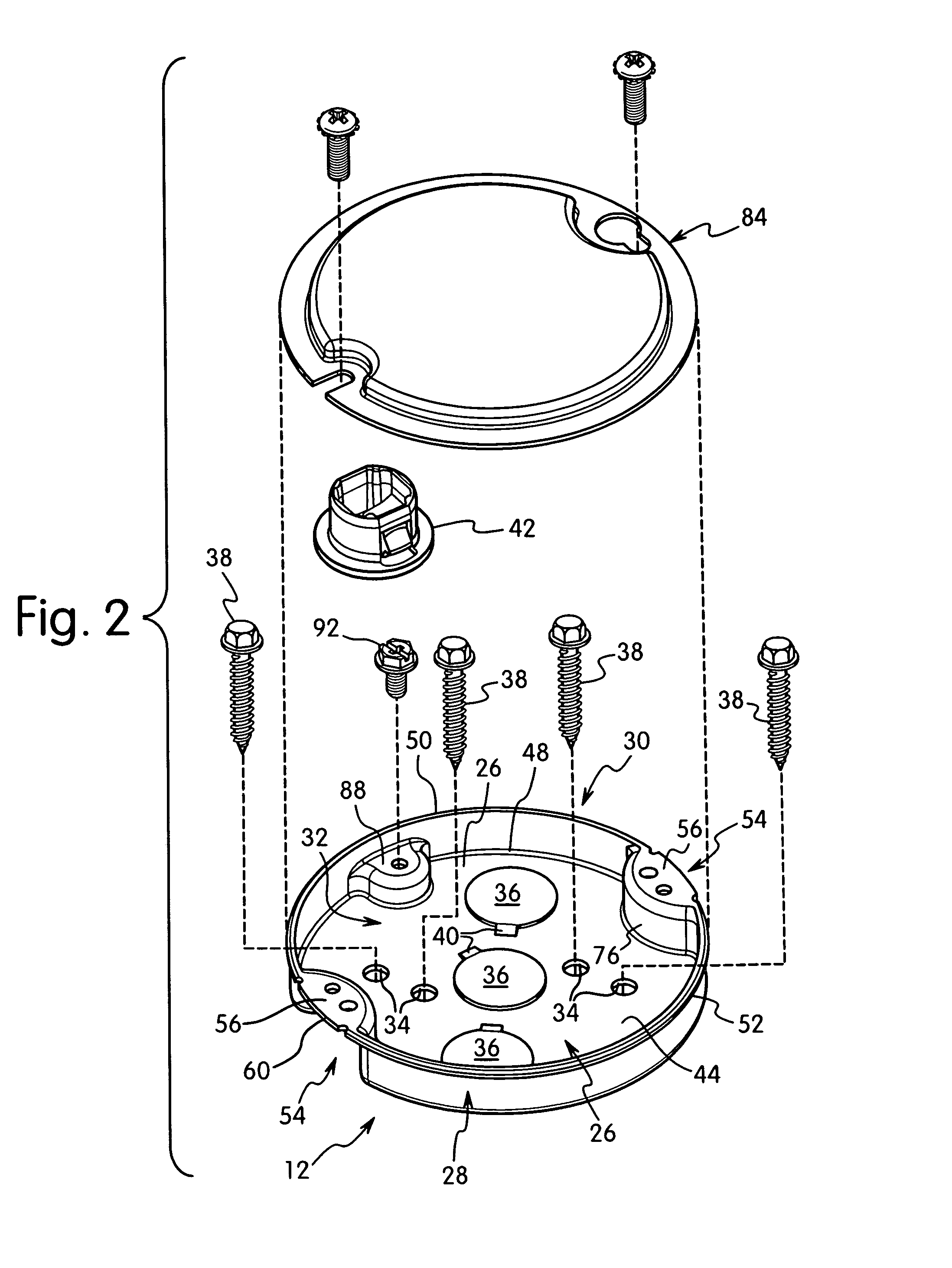
[0032]The present invention is directed to an electrical box and an electrical box assembly for supporting an electrical fixture. The invention is particularly directed to an electrical box having a plurality of mounting holes within the perimeter of the electrical box for receiving fasteners for coupling an electrical fixture to the electrical box. The electrical box typically includes knock-out plugs and mounting holes.

[0033]Referring to FIGS. 1–6, a first embodiment of the electrical assembly 10 is shown. Electrical assembly 10 includes an electrical box 12 for supporting an electrical fixture 14. Electrical fixture 14 is typically a ceiling fan or a light fixture. Electrical box 12 is mounted to a suitable support which can be a ceiling joist or other solid surface. In the embodiment illustrated, electrical box 12 is coupled to a support bracket 16 extending between a pair of ceiling joists 18. Bracket 16 as shown includes a pair of telescoping arms 20 to accommodate variations ...


PUM


Abstract

An electrical box has a side wall with at least one mounting flange that is contained completely within the perimeter of the side wall. The flange is coupled to the side wall along a common non-linear edge to resist bending of the flange along the joining edge with the side wall. In one embodiment, the electrical box has a substantially circular side wall with at least one recessed portion. The mounting flange is connected to the upper edge of the recessed portion and is positioned within a radius of the circular side wall.

Description

FIELD OF THE INVENTION[0001]The present invention is directed to an electrical box and to an electrical box assembly for supporting an electrical fixture. More particularly, the invention is directed to an electrical box having mounting holes within the perimeter of the box for supporting an electrical fixture such as a ceiling fan or light fixture.BACKGROUND OF THE INVENTION[0002]Electrical boxes are used to mount electrical fixtures such as ceiling fans and light fixtures. The electrical boxes commonly have tabs or flanges connected to a side wall that extend into the center of the box. The tabs include holes for receiving screws for fastening the electrical fixture to the box and for supporting the electrical fixture. The electrical box also encloses the wires and the electrical connections between the power supply and the electrical fixture. Care must be taken when mounting the electrical fixture to the electrical box to prevent the mounting screws from contacting and damaging t...

Claims


Application Information

Patent Timeline
Patent Type & Authority Patents(United States)
IPC IPC(8): H01H9/02
CPCH02G3/125H02G3/20Y10S248/906
Inventor JOHNSON, STEVEN J.KORCZ, KRZYSZTOF W.
Owner HUBBELL INC
Why Eureka
Try Eureka