Diffuser for a motor fan assembly

a technology of motor fan and diffuser, which is applied in the direction of machines/engines, stators, liquid fuel engines, etc., can solve the problems of negative effect, common noise, and unwanted noise generated during the process, so as to improve efficiency, improve system efficiency, and increase the effect of airflow

Active Publication Date: 2007-01-16
HEALTHY GAIN INVESTMENTS
View PDF4 Cites 23 Cited by
  • Summary
  • Abstract
  • Description
  • Claims
  • Application Information

AI Technical Summary

Benefits of technology

[0005]A diffuser is commonly used to slow the flow and to increase the static pressure of the working air stream after it leaves the outlet of the working air fan or impeller of a motor-fan assembly. The result of this increased static pressure rise (or suction) in a vacuum cleaner fan system is an increase in air-watts for a given amount of input power. While diffusers do a good job of improving system efficiency, they can have a negative effect in that unwanted noise can be generated during the process. This unwanted noise is commonly produced at the fan blade passing frequency. It has been found that a diffuser in which the vanes are oriented in an axial manner and not directly across from the fan blade tips can reduce or eliminate noise generated at the blade passage frequency. The vanes are axially arranged around the periphery of the diffuser to improve performance by converting air velocity into static pressure rise. The vanes also reduce noise by aligning the flow and making it more uniform. The flow is directed to radially arranged return vanes on the under side of the diffuser which further slows the flow and directs it to the interior of the motor for cooling.

Problems solved by technology

While diffusers do a good job of improving system efficiency, they can have a negative effect in that unwanted noise can be generated during the process.
This unwanted noise is commonly produced at the fan blade passing frequency.

Method used


Image

  • Diffuser for a motor fan assembly
  • Diffuser for a motor fan assembly
  • Diffuser for a motor fan assembly

Examples


Embodiment Construction

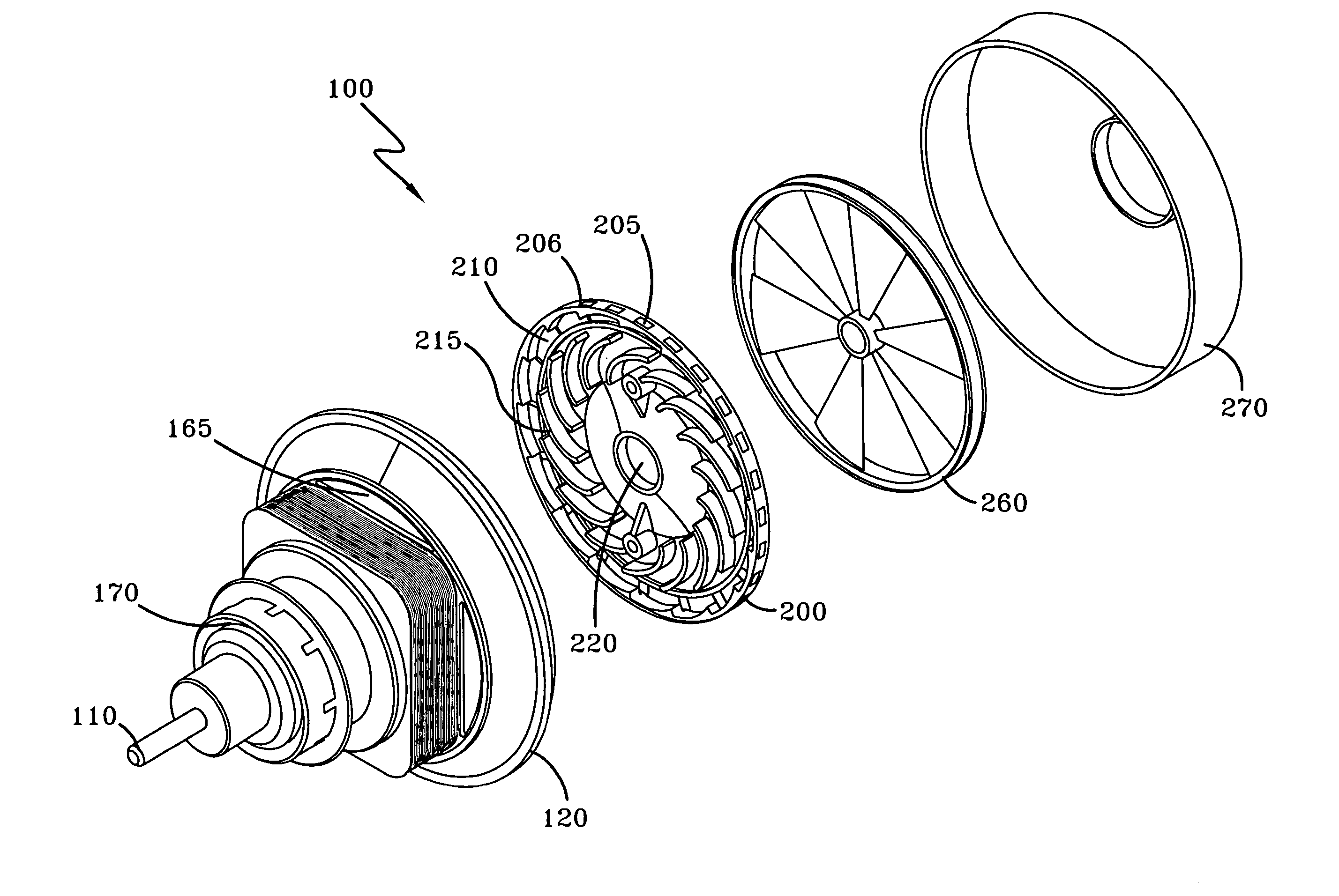
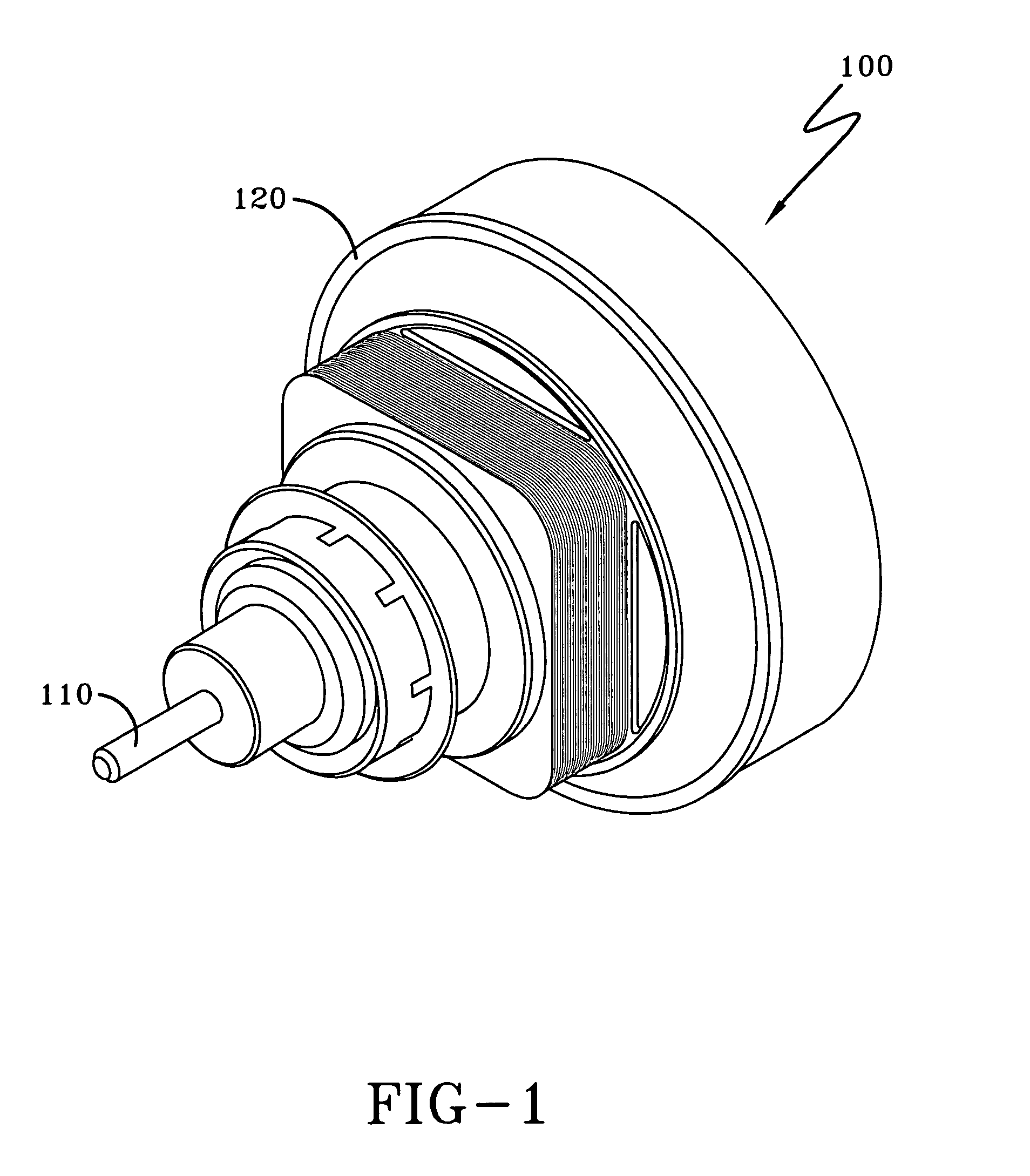
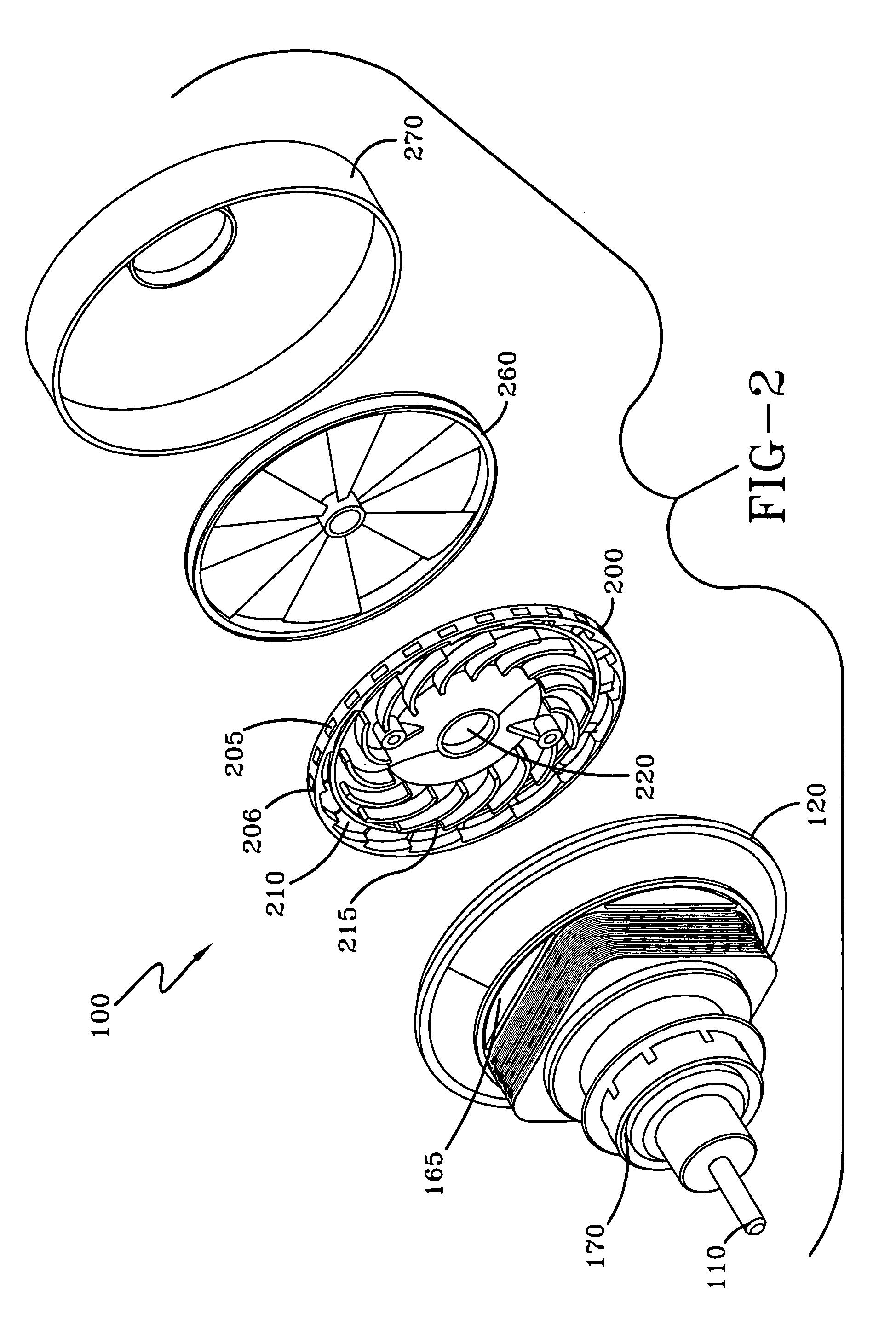
[0014]Referring now to FIG. 1, shown is a motor-fan assembly 100 for a floor care appliance such as an upright vacuum cleaner (not shown), according to the preferred embodiment of the present invention. Typically, a vacuum cleaner (not shown) includes a foot (not shown) and an upper housing assembly (not shown) pivotally connected to the foot (not shown). The foot (not shown) is similar to those known in the art and includes a nozzle opening (not shown) for receiving a stream of dirt-laden air and an agitator (not shown) for agitating and loosening dust and debris from a floor surface. The motor-fan assembly 100 creates the suction necessary to remove the loosened dust and debris from the floor surface. The motor-fan assembly 100 fluidly connects to the foot or suction nozzle (not shown) by a dirt duct (not shown). The upper housing assembly (not shown) houses a particle filtration and collecting system (not shown) for receiving and filtering the dirt-laden air stream which is creat...


PUM


Abstract

A floor care appliance is provided with a motor-fan assembly that includes a diffuser to improve efficiency but also reduces any resultant noise generated. The diffuser is disc shaped and has a plurality of equi-distant spaced vanes around the periphery. The vanes improve performance by converting air velocity into static pressure rise. The vanes also reduce noise by making the flow more uniform. A periphery of radially extending return vanes are arranged circumferentially on one side of the disc. The return vanes remove swirl and improve performance before directing the air through the interior of the motor for cooling.

Description

BACKGROUND OF THE INVENTION[0001]1. Field of the Invention[0002]This invention relates to floor car, and more specifically, to a diffuser for a motor-fan assembly for a floor care appliance.[0003]2. Summary of the Prior Art[0004]Floor care appliances are well known in the art. Typical floor care appliances include upright vacuum cleaners, canister vacuum cleaners, hard floor cleaners, and extractors. It is known to provide the motor-fan assembly for a floor care appliance with a diffuser for improving system efficiency. However, with the improvement in efficiency comes an increase in noise from the airflow. Therefore, there exists the need for a diffuser that improves efficiency but also reduces the associated generated noise. The present invention provides a diffuser that improves efficiency but also reduces the associated generated noise.SUMMARY OF THE INVENTION[0005]A diffuser is commonly used to slow the flow and to increase the static pressure of the working air stream after it...

Claims


Application Information

Patent Timeline
Patent Type & Authority Patents(United States)
IPC IPC(8): F04D29/44F04D17/00F04D29/54
CPCF04D29/542F04D29/544
Inventor KEGG, STEVEN W.
Owner HEALTHY GAIN INVESTMENTS
Why Eureka
Try Eureka