Method for adding an apparent non-signal line to a rapid diagnostic assay

a technology of apparent non-signal lines and rapid diagnostic assays, applied in the direction of analytical using chemical indicators, laboratory glassware, instruments, etc., can solve the problems of affecting the flow path of liquid, single-step devices obviating the necessity of performing complicated and time-consuming processing steps, and devices limited

Inactive Publication Date: 2007-02-20
QUIDEL
View PDF32 Cites 23 Cited by
  • Summary
  • Abstract
  • Description
  • Claims
  • Application Information

AI Technical Summary

Benefits of technology

[0037]The present invention achieves the “appearance” of a minus sign (−) by placing an indicator mark perpendicular to the test line, directly on the underlying support. The mark typically manifests with any sample flow, while the test line develops only with a positive sample flow. A further advantage of the present invention is the avoidance of a line that is substantially visible before the sample is added to the device.

Problems solved by technology

Single-step devices obviate the necessity of performing complicated and time consuming processing steps that may introduce errors in the end result.
A portion of the chromatographic medium is removed, or otherwise partially blocked, thereby affecting the flow path of the liquid.
Such devices are limited as the test strips may present a line that is visible before the sample is added.
Previous methods are further disadvantaged as the additional manufacturing step involves a difficult placement procedure to orient the perpendicular line directly in the center of the viewing window.
Whether the perpendicular line is a printed minus sign, or a reagent-based control line, this approach is particularly ill suited for certain matrix construction procedures, including web processing methods that involve a continuous flow or continuous roll application approach.
While conceivably workable in some circumstances, the previous detection systems that employ transparent membranes are of limited utility.

Method used


Image

  • Method for adding an apparent non-signal line to a rapid diagnostic assay
  • Method for adding an apparent non-signal line to a rapid diagnostic assay
  • Method for adding an apparent non-signal line to a rapid diagnostic assay

Examples


example 1

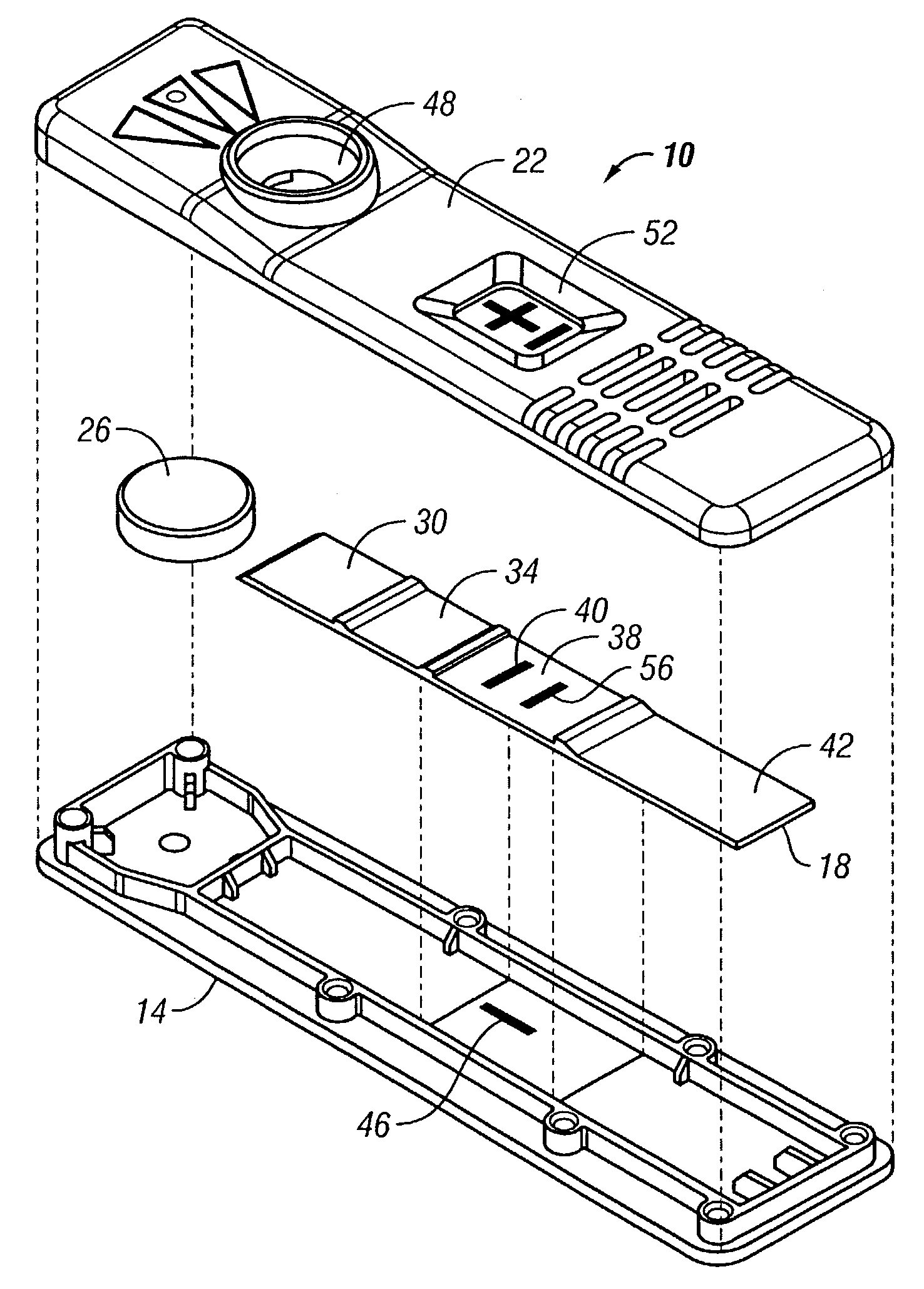
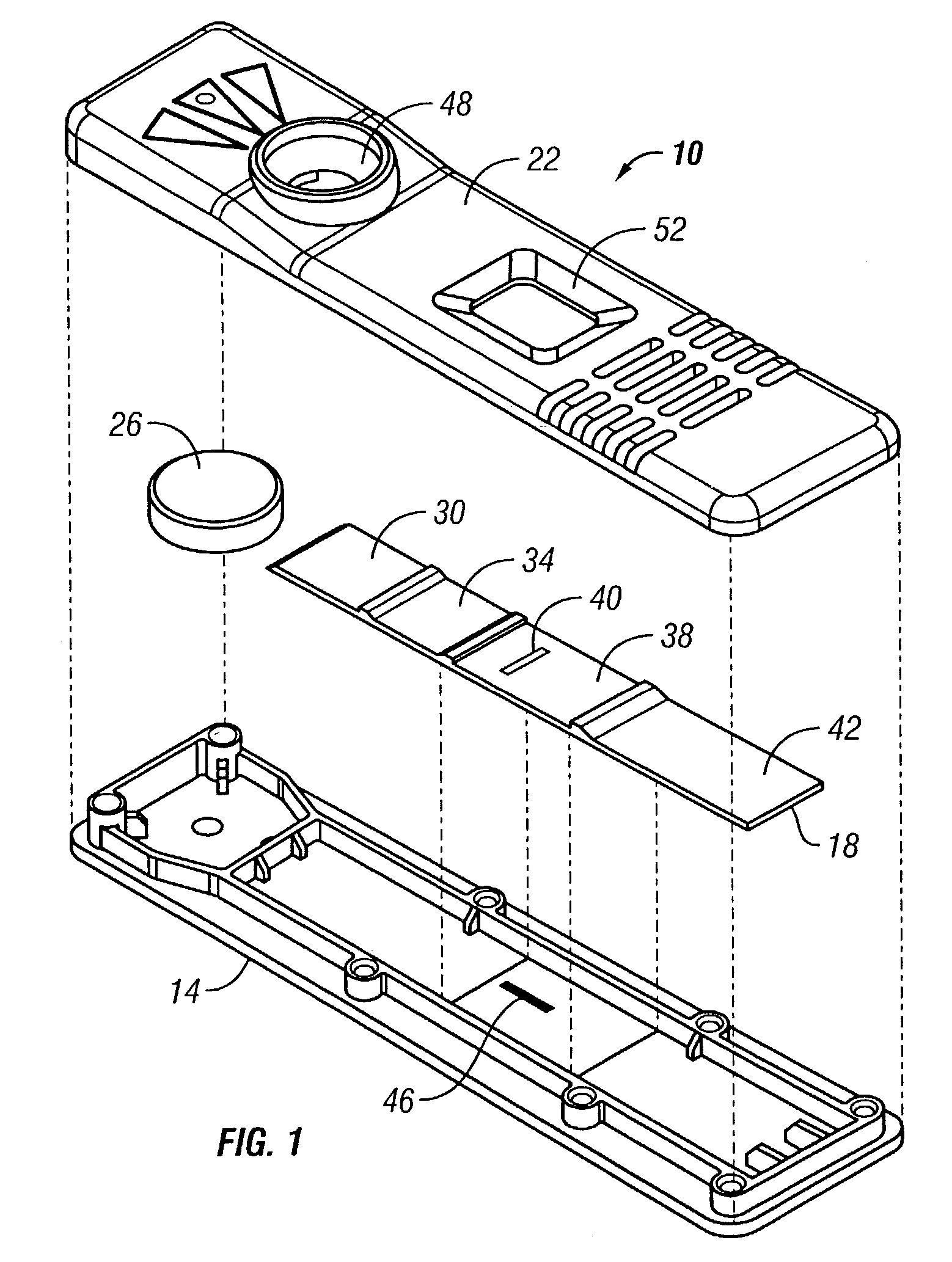
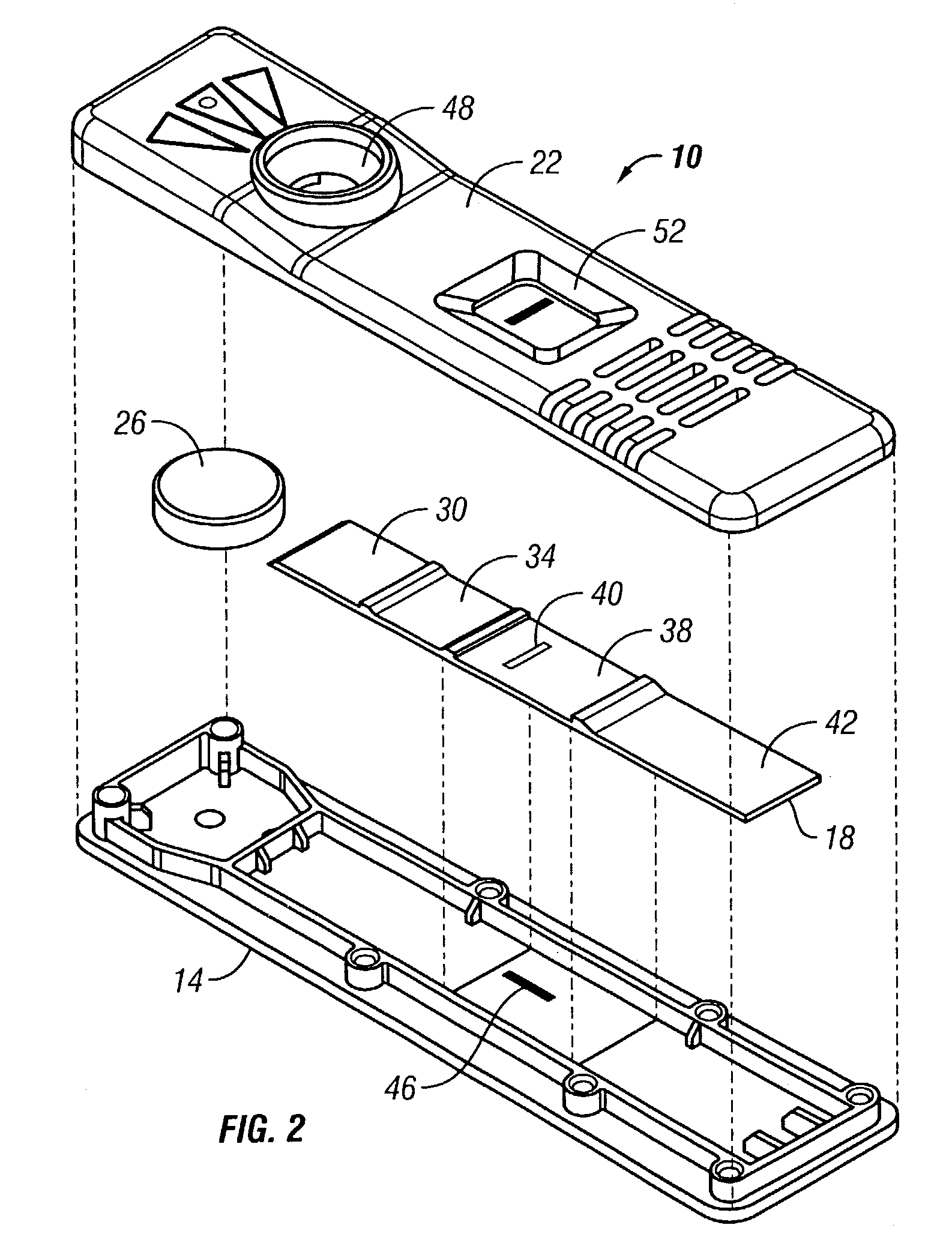
[0157]A lateral flow test device was constructed according to principles of the present invention. The test device included a G-III plastic bottom (#Z0846500), a G-III plastic scanner top (#Z0440900), a sample pad containing stock assay reagent, a label pad containing stock assay reagent, an observation zone as described below, and an absorbent pad (#0841000).

[0158]A nitrocellulose web assembly membrane from Millipore, trade name Highflow Plus Membrane, was combined with a clear Mylar backing.

[0159]A dark line was made on the inside of the plastic bottom, positioned parallel to sample flow in approximately the same area as would be underneath the fixed minus line from a current assay strip.

[0160]This bottom was then assembled with an experimental G-IV assay strip as described above, and a plastic scanner top. When a liquid sample was added to the test unit, the dark line, which was barely visible through the dry strip, became clearly visible. The results are shown generally in FIG. ...

example 2

[0161]Goat anti-alpha hCG antibodies were immobilized on Hi-flow plus nitrocellulose membrane (nitrocellulose membrane cast on a transparent nylon sheet), manufactured by Millipore Inc. A second, unrelated protein was immobilized on the membrane for the procedural control line. The membrane was then blocked with a protein solution and dried prior to assembly.

[0162]A sample pad (non-woven rayon fiber backed with mylar) was impregnated with a buffered protein solution and dried.

[0163]The label pad (non-woven rayon fiber backed with mylar) was impregnated with a solution containing red colored polystyrene microspheres coated with anti-beta hCG monoclonal antibodies, blue colored polystyrene microspheres coated with a binding pair member to the control line protein, and stabilizing agents followed by a drying process.

[0164]The sample and label pad, the capture membrane and an absorbent pad were then assembled into a test strip similar to FIG. 4.

[0165]A visible line was printed onto the ...


PUM

PropertyMeasurementUnit
pore diameteraaaaaaaaaa

Abstract

A test device and method for determining the presence or absence of one or more analytes in a fluid sample, the test device including a support or member bearing a mark thereon, and a matrix or member containing a capture zone. In operation, an observation area in the test device becomes transparent, thereby allowing the user to view a mark that is present on a support that is disposed beneath the observation area. Typically, the mark on the underlying support is configured as a minus (−) sign. In the absence of analyte in the sample, the test device presents a negative result as a minus (−) signal. In the presence of analyte in the sample, however, the mark operates in concert with a perpendicular test line on the observation area to present a positive result as a plus (+) signal that is visible to the user.

Description

CROSS-REFERENCE TO RELATED APPLICATIONS[0001]The present application is a continuation-in-part of U.S. application Ser. No. 09 / 950,366; filed Sep. 10, 2001, now U.S. Pat. No. 6,855,561, which is incorporated herein by reference.BACKGROUND OF THE INVENTION[0002]The present invention relates generally to devices and methods for detection of analytes in test samples. More specifically, the present invention provides solid phase test devices and methods that combine an internal indicator on the test with an external mark located on a support.[0003]Various analytical procedures and devices are commonly employed in detection assays to determine the presence and / or amount of substance of interest or clinical significance which may be present in biological or non-biological fluids. Such substances are generally termed “analytes” and can include antibodies, antigens, drugs, or hormones.[0004]The present invention includes, but is not limited to, lateral flow chromatography assay formats. Gen...

Claims


Application Information

Patent Timeline
Patent Type & Authority Patents(United States)
IPC IPC(8): G01N33/533G01N21/86G01N33/543G01N33/558
CPCG01N21/8483G01N33/54386G01N33/558B01L3/5023Y10T436/25125Y10S435/805Y10S436/81Y10S435/823Y10S436/823Y10S436/807G01N33/54388
Inventor JEROME, JEREMYDAQUIPA, MARKJACONO, BRUCEBOEHRINGER, HANSLAMBOTTE, PAULLAWRENCE, PAUL J.
Owner QUIDEL
Why Eureka
Try Eureka