Connector and receptacle containing a physical security feature

a technology of physical security and connectors, applied in the field of connectors, can solve the problems that the optical communication system neither generates nor is susceptible to electromagnetic interference, and achieve the effect of imparting physical security

Active Publication Date: 2007-02-27
COMMSCOPE TECH LLC
View PDF3 Cites 55 Cited by
  • Summary
  • Abstract
  • Description
  • Claims
  • Application Information

AI Technical Summary

Benefits of technology

[0006]The present invention provides for a connector system that provides discriminating mating among similar, but different, plugs and receptacles by using a system of geometrically matched connector components which allows certain combinations of plugs and receptacles—i.e., mating pairs—to mate while preventing other combinations from mating. Such a system of mutually-exclusive mating pairs provides for a number of benefits. First, it imparts physical security to a particular network by ensuring that only authorized users who possess a particular connector component can connect to the particular network. Second, the present invention may be employed in the manufacture of devices, requiring fibers or wires to be connected in particular and complex arrangements. In other words, the discriminating connectors of the present invention can be engineered into a system such that, during manufacturing, the correct connection of the fibers / wires is ensured by the mating pairs and their ability to prevent all other “incorrect” connections. Applications requiring particular and complex routing of fibers or wires include, for example, routers, backplane assemblies, and even component devices such as multiplexers / demultiplexers.

Problems solved by technology

Additionally, optical communication systems neither generate nor are susceptible to electromagnetic interference (EMI).

Method used


Image

  • Connector and receptacle containing a physical security feature
  • Connector and receptacle containing a physical security feature
  • Connector and receptacle containing a physical security feature

Examples


Embodiment Construction

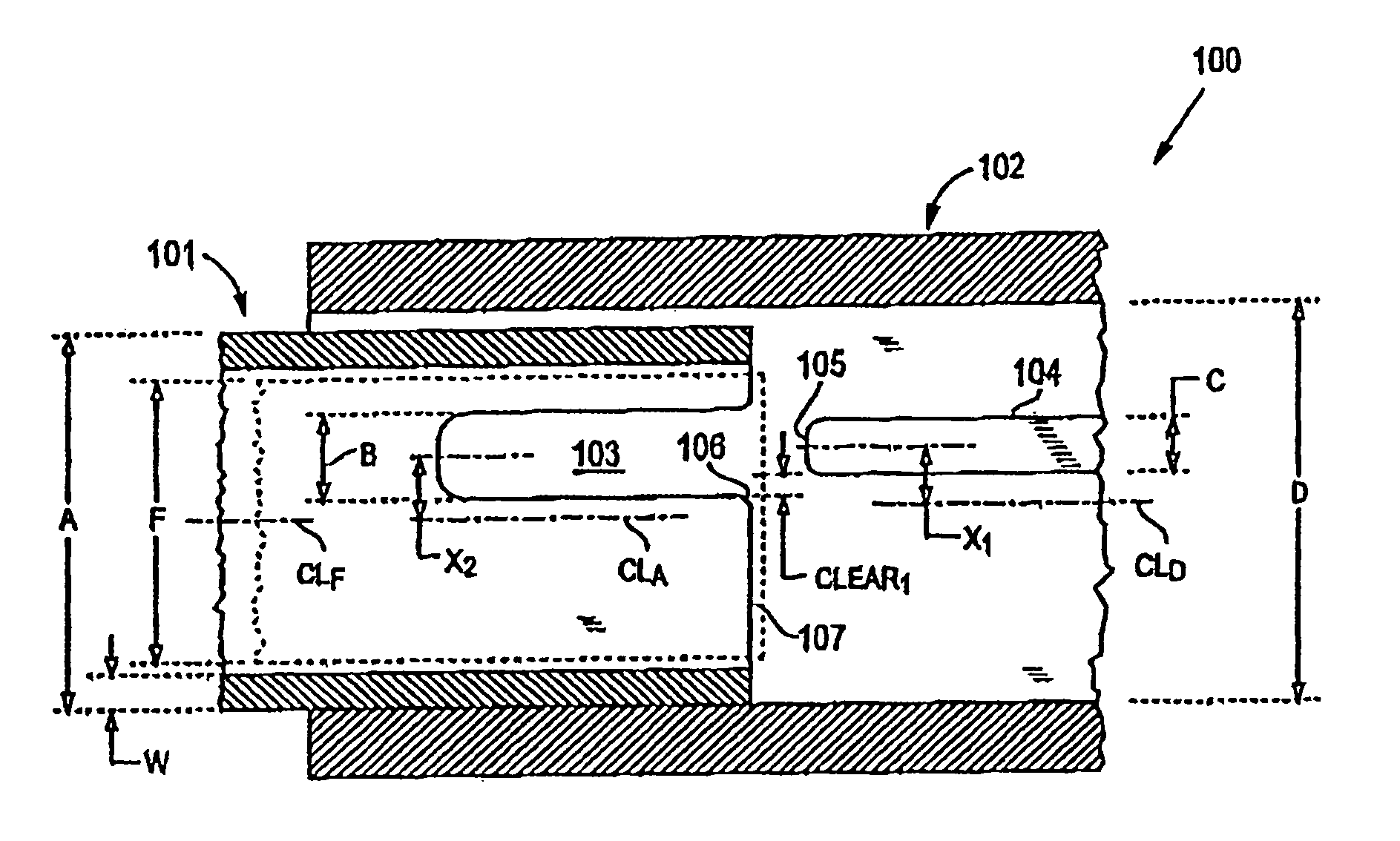
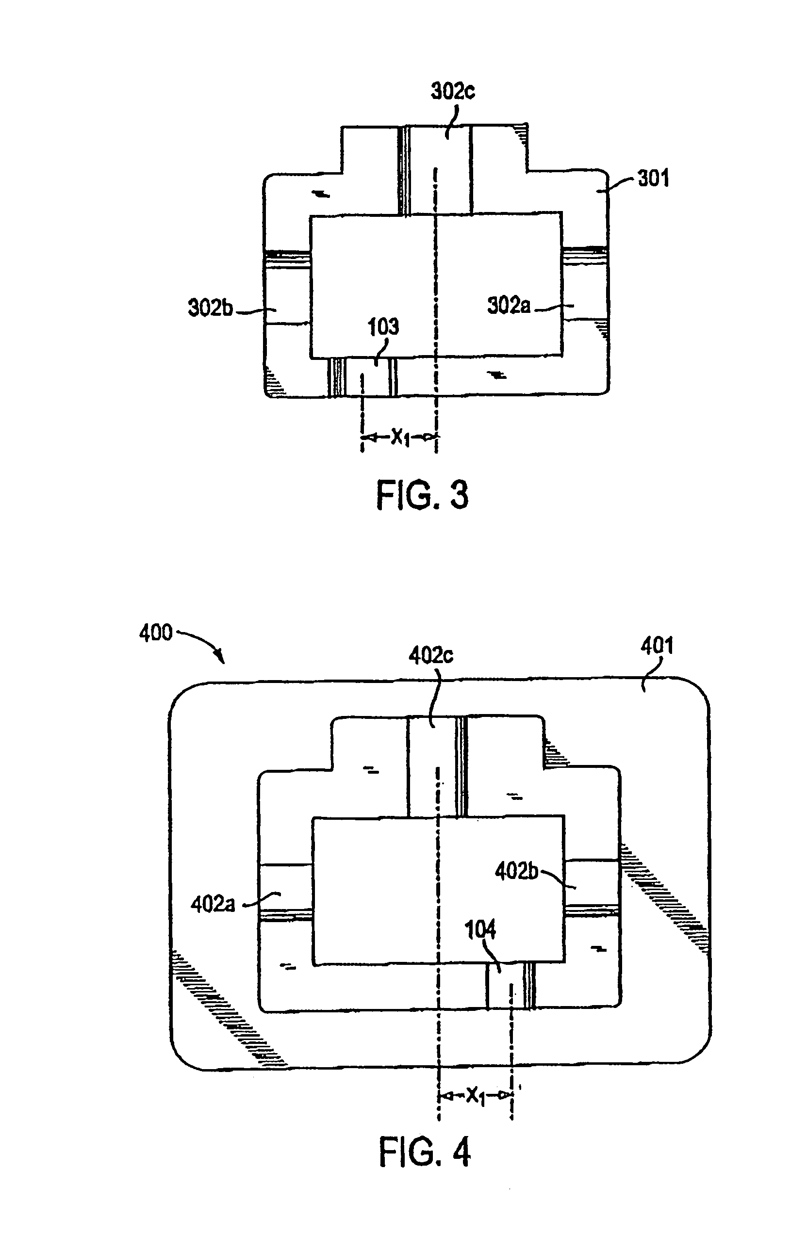
[0018]The present invention relates to a connector system comprising plugs and receptacles which mate in a discretionary way such that components form mating pairs selectively among the various components. Referring to FIGS. 1–4, a preferred embodiment of the connector system of the invention is shown. The connector system comprises a plurality of receptacles and a plurality of plugs (one of each is shown in FIG. 1). Each receptacle has an inner surface with a first geometry. A certain number of receptacles have different first geometries. Each plug has a second geometry, with a certain number of second geometries being different. Each different first geometry corresponds to one, and only one, second geometry such that the plugs and receptacles of corresponding first and second geometries are mating pairs. Therefore, the first and second geometries cooperate to allow only certain pairs of plugs and receptacles to mate (herein “mating pairs,”“mating plug and receptacle,” or “keyed pa...


PUM


Abstract

An optical network comprising: (a) a plurality of different optical fiber receptacles for facilitating an optical connection to different information networks requiring different access authorization, each different optical fiber receptacle optically coupled to one and only one different information network, each optical fiber receptacle having an inner surface with a first geometry, the first geometry comprising at least a slot, a certain number of optical fiber receptacles having different first geometries in which the slots are in different positions; and (b) a plurality of different optical fiber plugs for optically coupling with the different optical fiber receptacles, each optical fiber plug having a second geometry, the second geometry comprising at least a key in a certain position, the certain number of optical fiber plugs having different second geometries in which the keys are in different positions, each different first geometry corresponding to one and only one second geometry such that the optical fiber plugs and receptacles of corresponding first and second geometries are mating pairs.

Description

CROSS REFERENCE TO RELATED APPLICATIONS[0001]This application claims priority to U.S. Provisional Application No. 60 / 218,705, filed Jul. 17, 2000 and to copending U.S. application Ser. No. 09 / 908,140 filed Jul. 17, 2001 both of which are hereby incorporated by reference.FIELD OF THE INVENTION[0002]The present invention relates generally to connectors for use in telecommunication networks, and, more specifically, to a connector system in which only certain plugs can mate with certain receptacles to provide discriminating access to particular networks.BACKGROUND OF THE INVENTION[0003]Fiber optic communication systems have become increasing more popular in recent years as fiber optic technology offers several advantages over the conventional copper wire-based technology. For example, fiber optic communication systems provide substantially increased bandwidth, allowing large volumes of data to be transferred quickly over long distances. Additionally, optical communication systems neithe...

Claims


Application Information

Patent Timeline
Patent Type & Authority Patents(United States)
IPC IPC(8): G02B6/38
CPCG02B6/3831G02B6/3869
Inventor ABENDSCHEIN, FREDERIC H.GURRERI, MICHAEL LAWRENCE
Owner COMMSCOPE TECH LLC
Why Eureka
Try Eureka