Power amplifier control technique for enhanced efficiency

a technology of power amplifiers and control techniques, applied in the direction of gain control, amplification control device circuits, modulation, etc., can solve the problems of requiring a significant amount of power, and achieve the effects of reducing the output power of the power amplifier, increasing the gain of the final amplifier stage, and reducing the variable supply voltage provided to the one or more input amplifier stages

Active Publication Date: 2007-03-20
QORVO US INC
View PDF14 Cites 91 Cited by
  • Summary
  • Abstract
  • Description
  • Claims
  • Application Information

AI Technical Summary

Benefits of technology

[0005]In this embodiment, the final amplifier stage operates in either saturation mode or linear mode based on a radio frequency (RF) power of an amplified signal provided to the final amplifier stage from the one or more input amplifier stage. More specifically, as output power of the power amplifier is reduced from its highest power level, the variable supply voltage provided to the one or more input amplifier stages is reduced. As a result, the RF power of the amplified signal provided to the final amplifier stage decreases, a...

Problems solved by technology

However, due to its inherent nature, the power amplifier requires a significant amou...

Method used


Image

  • Power amplifier control technique for enhanced efficiency
  • Power amplifier control technique for enhanced efficiency
  • Power amplifier control technique for enhanced efficiency

Examples


Embodiment Construction

[0017]The embodiments set forth below represent the necessary information to enable those skilled in the art to practice the invention and illustrate the best mode of practicing the invention. Upon reading the following description in light of the accompanying drawing figures, those skilled in the art will understand the concepts of the invention and will recognize applications of these concepts not particularly addressed herein. It should be understood that these concepts and applications fall within the scope of the disclosure and the accompanying claims.

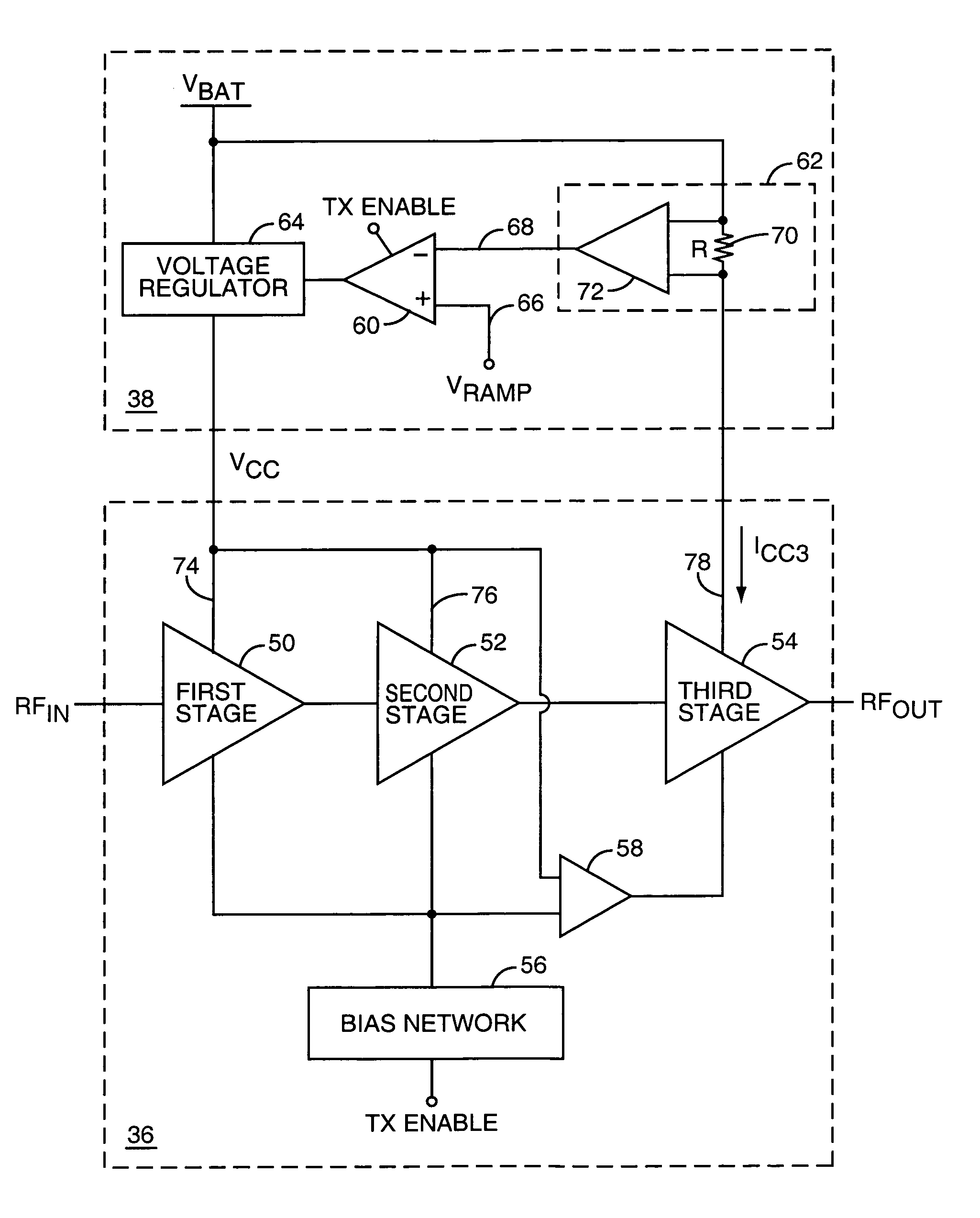
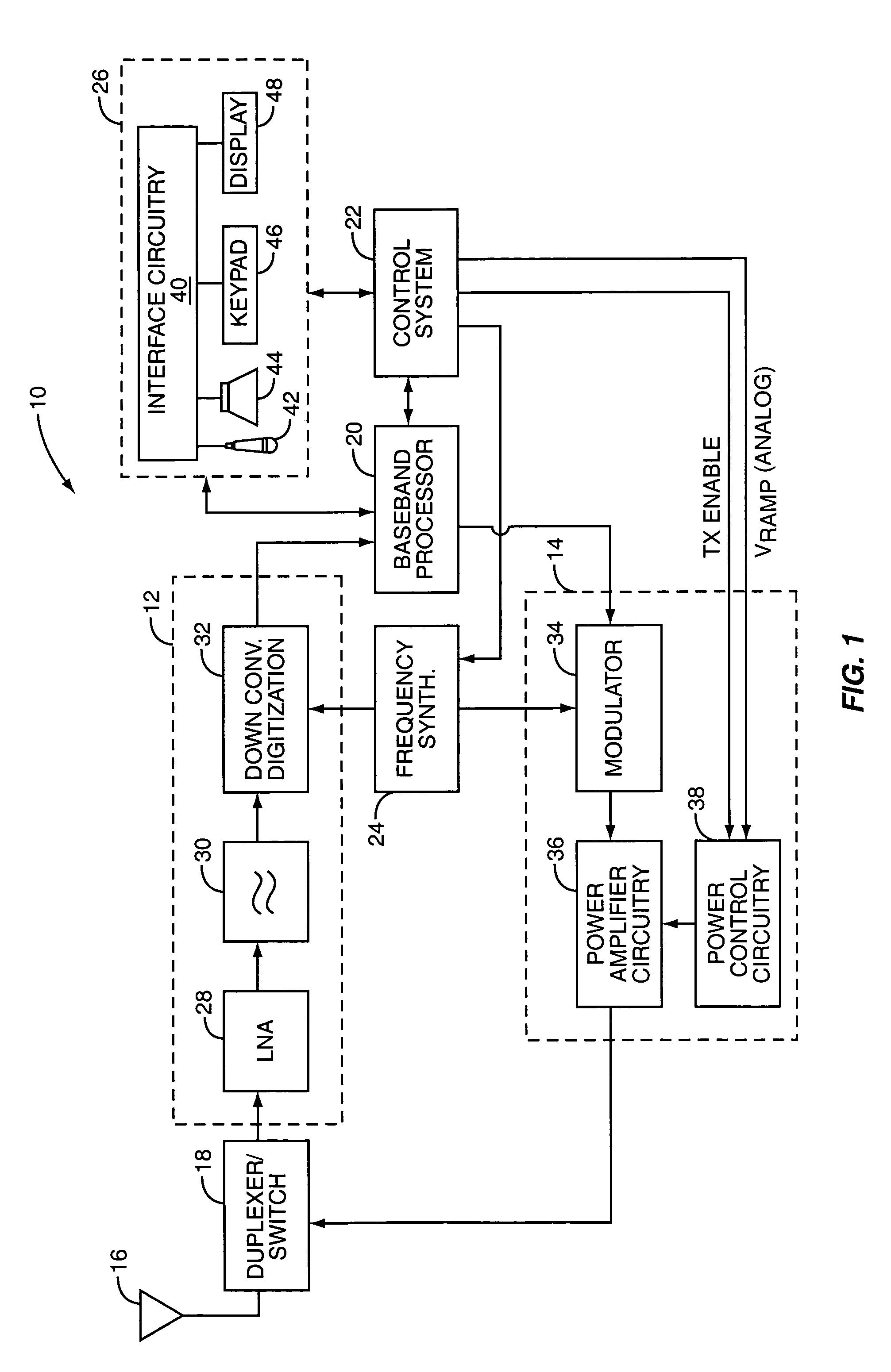
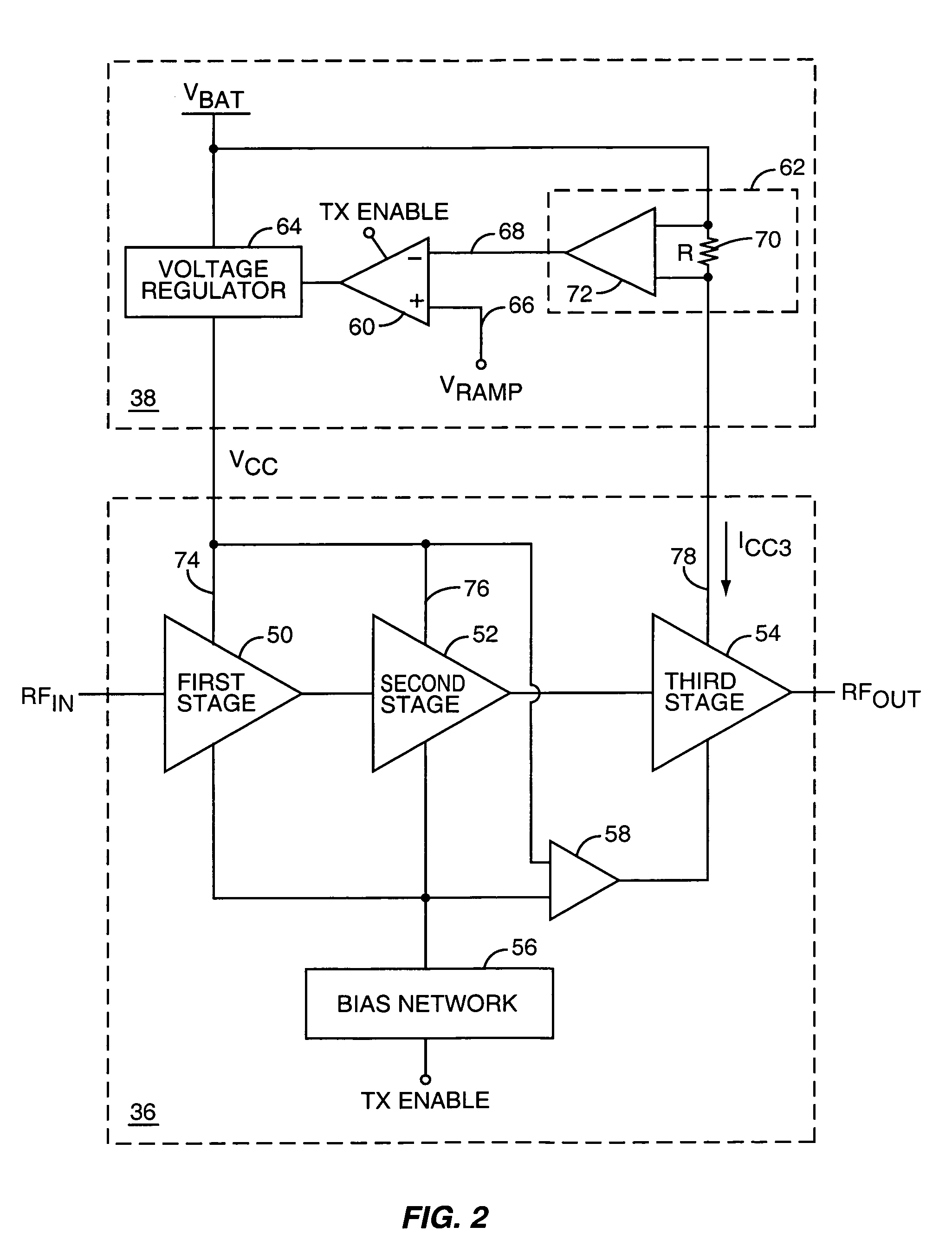
[0018]The present invention is preferably incorporated in a mobile terminal 10, such a mobile telephone, personal digital assistant, or the like. The basic architecture of a mobile terminal 10 is represented in FIG. 1 and may include a receiver front end 12, a radio frequency transmitter section 14, an antenna 16, a duplexer or switch 18, a baseband processor 20, a control system 22, a frequency synthesizer 24, and an interface 26...


PUM


Abstract

A power amplifier configuration including power amplifier circuitry and power control circuitry and having improved Power Added Efficiency (PAE) is provided. The power amplifier circuitry includes one or more input amplifier stages in series with a final amplifier stage. The power control circuitry provides a variable supply voltage to the input amplifier stages based on an adjustable power control signal. The final amplifier stage is powered by a fixed supply voltage. In operation, as output power of the power amplifier is reduced from its highest power level, the variable supply voltage is reduced. Accordingly, RF power of an amplified signal provided to the final amplifier stage from the input amplifier stages decreases, and the final amplifier stage transitions from saturation to linear operation, thereby increasing the gain of the final amplifier stage. Thus, a desired output level can be maintained while operating at lower current levels.

Description

FIELD OF THE INVENTION[0001]The present invention relates to radio frequency (RF) power amplifiers and more particularly relates to an RF power amplifier having enhanced efficiency.BACKGROUND OF THE INVENTION[0002]In recent years, worldwide demand for wireless cellular communications has increased dramatically. Mobile terminals manufactured to meet this burgeoning demand must adhere to standards such as the Global System for Mobile Communications (GSM) standard. Another standard, the Digital Cellular System (DCS) standard is based on GSM, but is directed towards higher cell density and lower power. A third standard, Personal Communications Services (PCS), is a “catch all” for many digital cellular systems, including GSM, operating in North America. These standards all require precise output power control over a large dynamic range in order to prevent a transmitter located in one cell from interfering with the reception of transmissions from other transmitters in neighboring cells.[0...

Claims


Application Information

Patent Timeline
IPC IPC(8): H03G3/10
CPCH03C5/00H03G3/3047H03F1/0211H03F1/0233H03F3/24H03G1/0005H03G3/004H03G3/3042H03F1/0205H03F2200/105H03F2200/408H03F2200/465H03F2200/481H03F2200/504H03F2200/78
Inventor EPPERSON, DARRELL G.GAMERO, CARLOSBOSLEY, RYANGIBSON, JOEL R.LABELLE, MICHAELYODER, SCOTT
Owner QORVO US INC
Why Eureka
Try Eureka