Flow restriction device

a flow restriction and liquid flow technology, applied in the direction of liquid transfer devices, valve operating means/releasing devices, transportation and packaging, etc., can solve the problems of operator exposure to potentially hazardous solutions, difficulty in changing the flow rate of liquid, and difficulty in removing components, so as to avoid the need for electrical power and/or relatively complex electronics

Active Publication Date: 2007-04-10
JOHNSONDIVERSEY INC
View PDF19 Cites 2 Cited by
  • Summary
  • Abstract
  • Description
  • Claims
  • Application Information

AI Technical Summary

Benefits of technology

[0009]An object of the present invention is to provide a liquid flow-restriction device which permits easy and quick selection of one of multiple differing flow passages, preferably not requiring electrical power and preferably offering different flow rates.
[0013]To obtain automatic selection of the appropriate flow rate and / or the appropriate liquid to be dispensed into a particular container, the liquid dispenser may have control means for moving the actuating element of the flow-restriction device with respect to the valve members to open a desired one of the flow-restriction passages, the control means operating in dependence on codes provided on respective containers presented to the liquid dispenser to receive liquid. The control means may be mechanical, avoiding the need for electrical power and / or relatively complex electronics.

Problems solved by technology

This method of flow regulation has several disadvantages primarily due to the fact that it is difficult to change the flow rate of liquid to be diluted in the eductor.
This is because it is difficult and time-consuming to remove the component which carries the flow restricting channel and replace it with a flow restricting component for a different flow rate.
Partial dismantling of the eductor can result in spillage of the solution being diluted, so that the operator may become exposed to the potentially hazardous solution.

Method used


Image

  • Flow restriction device
  • Flow restriction device
  • Flow restriction device

Examples


Embodiment Construction

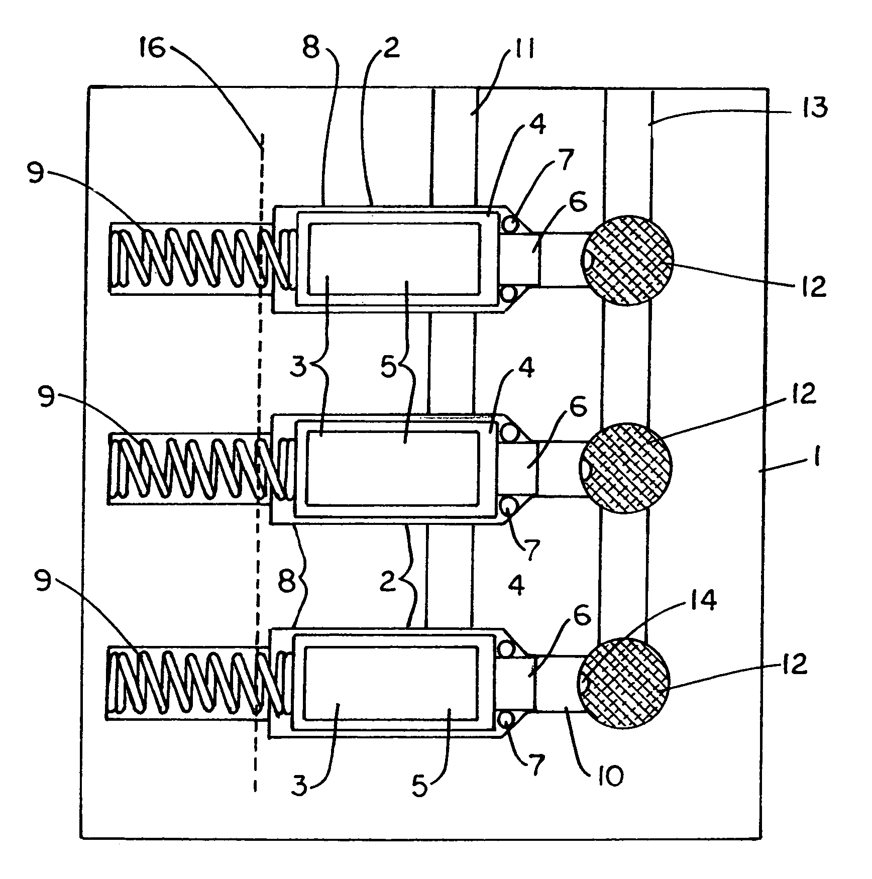
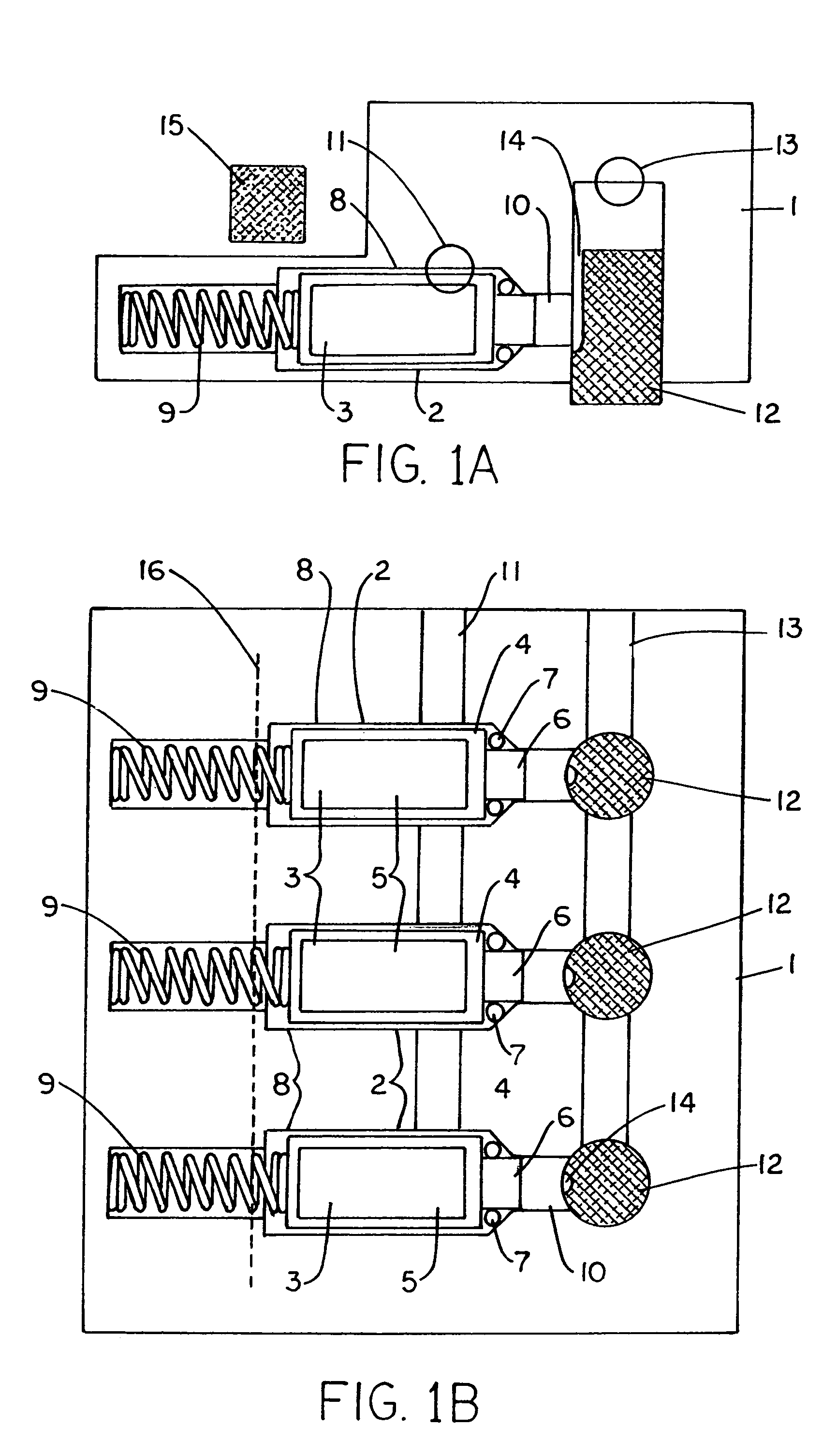
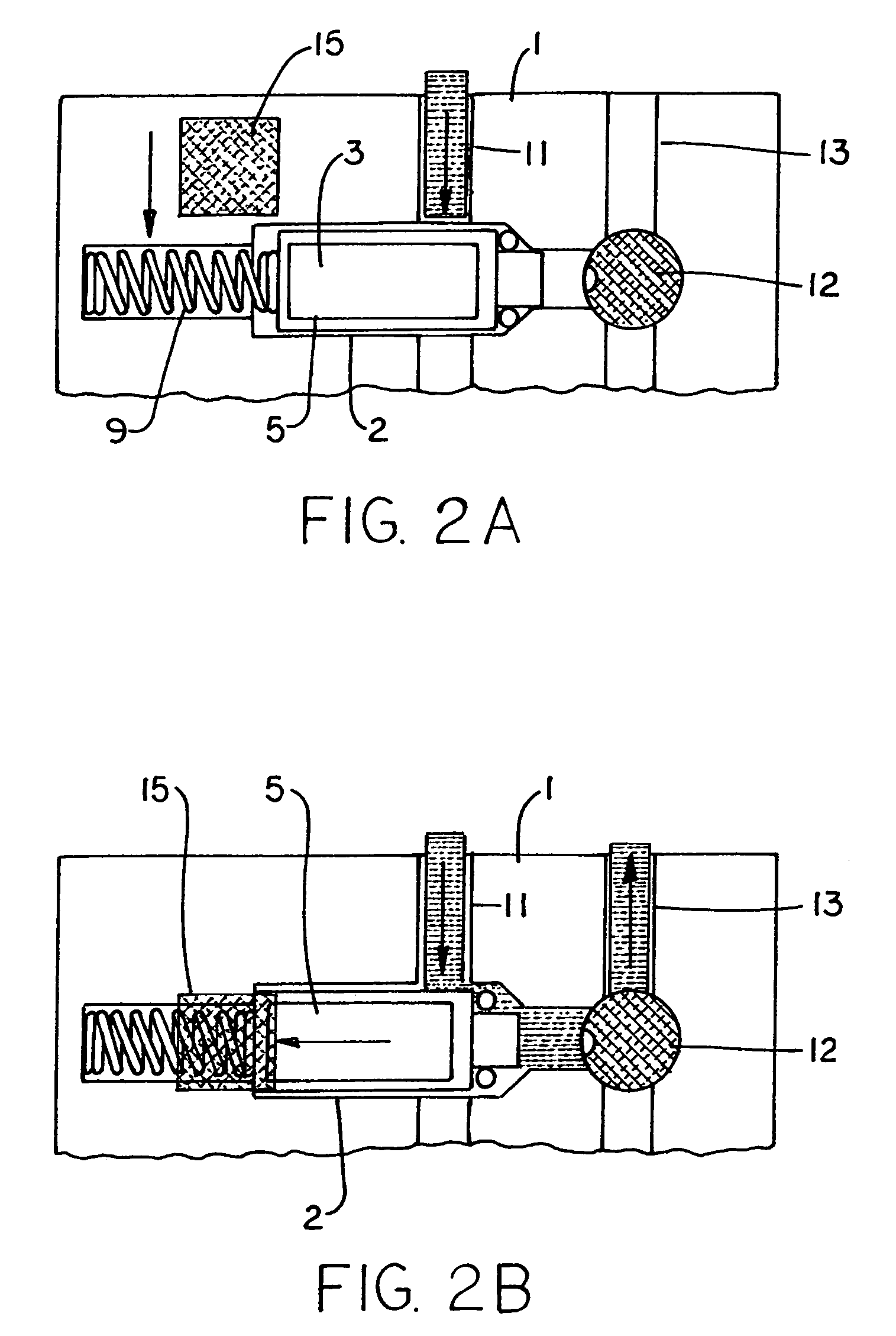
[0018]The flow restriction device embodying the invention shown in the figures has a body 1 formed of moulded plastics components and having within it interconnecting cavities for receiving other components and providing liquid flow paths. Located within cavities 8 of the body are three magnetically operated valves 2, each having a valve member 3 in the form of a moulded plastics body 4 containing a body of magnetisable material 5, such as soft iron and having a projection 6 at one end surrounded by an O-ring seal 7. The valve member 3 is slidable within the cavity 8 and biased by a spring 9 into the closed position of the valve in which the O-ring 7 abuts a tapering shoulder of the cavity 8 and in which the extremity of the projection 6 is received in a passage 10 which is an outlet from the valve cavity 8.

[0019]The cavities 8 of the three valves 2 are connected to a common inlet 11 of the flow-restriction device. They are also connected, via the passages 10 and flow restrictors 12...


PUM


Abstract

A liquid flow-restriction device has a plurality of flow-restriction passages connected to a common outlet. Each flow-restriction passage has a magnetically operable valve having a valve member movable between an open position and a closed position. The valves are operated by a common actuating element selectively positionable with respect to the valve members to open the valves. The actuating element is a permanent magnet. The device is simple and allows easy selection of a flow rate to a dilution dispenser.

Description

CROSS-REFERENCE TO RELATED APPLICATIONS: NONESTATEMENT REGARDING FEDERALLY SPONSORED RESEARCH OR DEVELOPMENT: NONE[0001]1. Field of the Invention[0002]This invention relates to the field of liquid flow rate regulation, e.g. restriction of the flow rate of the liquid in the supply line of a chemical diluting device, such as an eductor or the like. The invention also relates to a liquid dispenser having such a flow-restriction device.[0003]2. Background of the Invention[0004]It is common practice in many industries, such as hotels and catering, for chemicals such as those used for cleaning to be purchased as concentrated liquids and then diluted with water to give the correct concentrations for use. Proportioning dispensing apparatus have been designed to achieve the desired dilution of the concentrated solution and dispense the mixed diluted solution.[0005]These dispensers have commonly employed venturi-type devices, known as eductors, to aspirate or draw the concentrated solution in...

Claims


Application Information

Patent Timeline
Patent Type & Authority Patents(United States)
IPC IPC(8): B67D5/06B67D7/06B67D7/34B67D7/74F16K1/00F16K31/08
CPCB67D7/344B67D7/741F16K31/086F16K11/18F16K31/06
Inventor CROSSDALE, GARRY WILLIAMWEBB, CHRISTOPHER JOHN
Owner JOHNSONDIVERSEY INC
Why Eureka
Try Eureka