Signal assembly

a technology of sign assembly and assembly plate, which is applied in the direction of point-like light source, electric lighting with batteries, and support devices for lighting, etc., can solve the problem of too large to be held by users when needed

Inactive Publication Date: 2007-05-29
WANG SHIUNN TERNY
View PDF9 Cites 59 Cited by
  • Summary
  • Abstract
  • Description
  • Claims
  • Application Information

AI Technical Summary

Problems solved by technology

The conventional signal assembly is mainly focused on a stationary waning purpose and is too big to be held by the users when needed.

Method used


Image

  • Signal assembly
  • Signal assembly
  • Signal assembly

Examples


Embodiment Construction

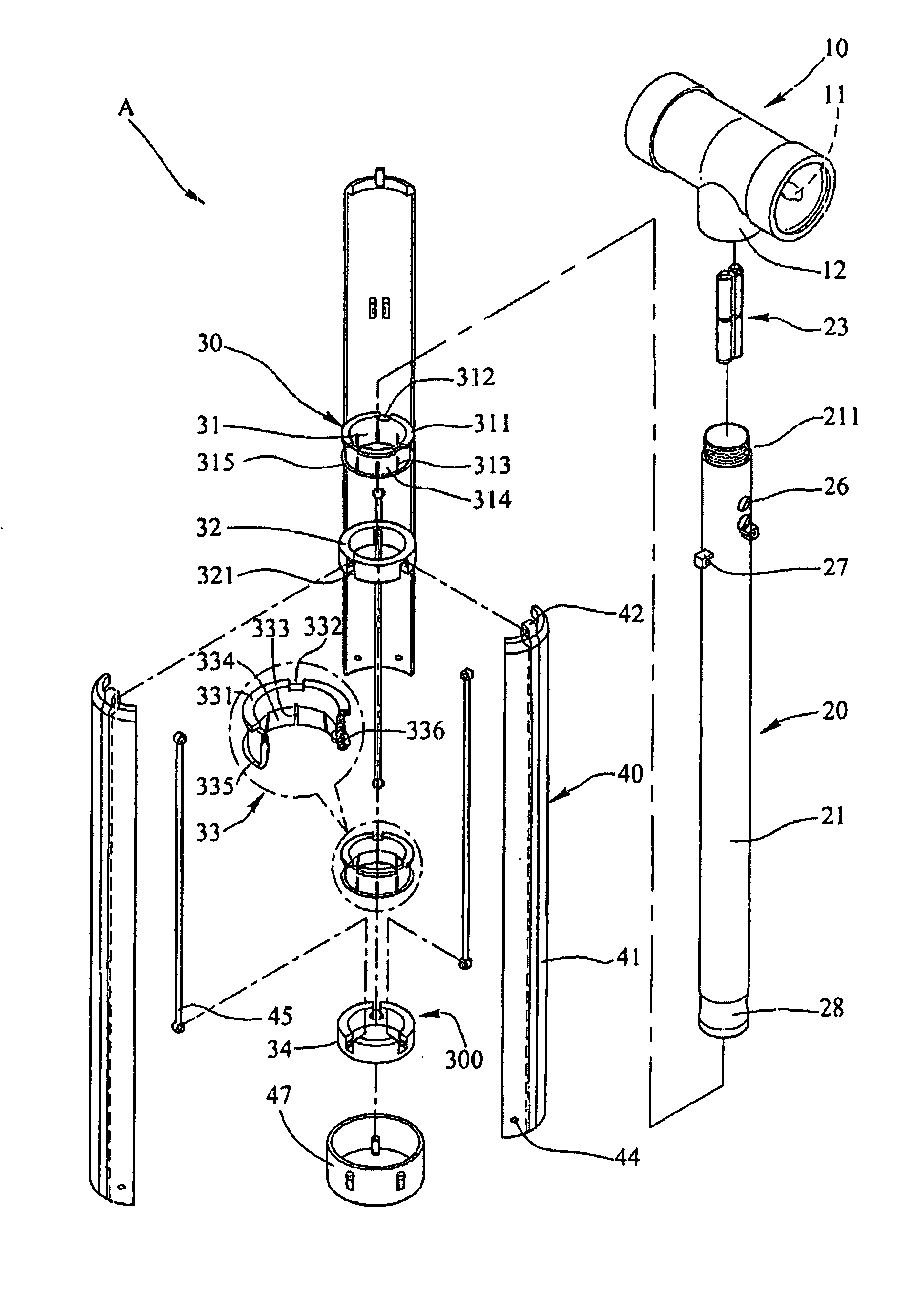
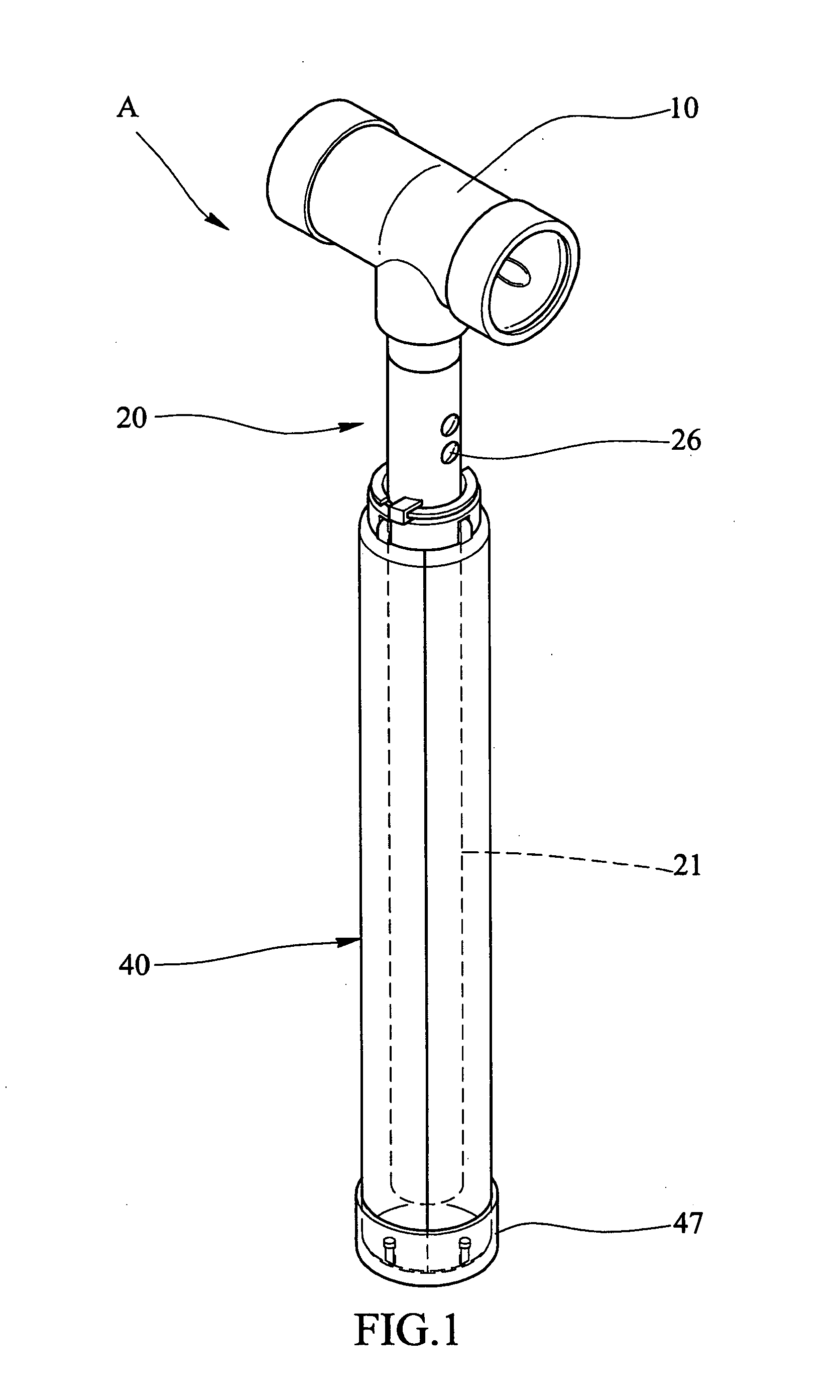
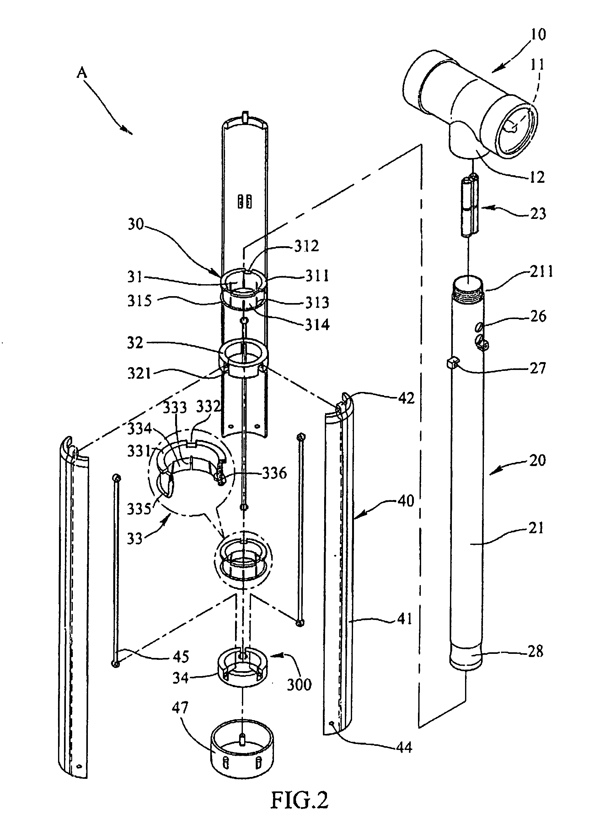
[0015]Referring to FIGS. 1 to 3, the signal assembly “A” of the present invention comprises a light device 10 that is a tubular member with two light bulbs 11 on two ends thereof and a connection neck 12 extends from a mediate portion of the light device 10. A light stick 20 is a transparent or semi-transparent tube 21 and has a threaded portion 211 on a first end thereof so that the connection neck 12 is threadedly connected with the threaded portion 211 of the light stick 20. A battery pack 23 and a light bulb 25 are received in an interior 22 of the light stick 20. A control circuit board 24 is electrically connected to the battery pack 23 and a light bulb 25. The other end of the battery pack 23 is connected to a conductive plate 13 in the connection neck 12 and the two light bulbs 11 are electrically connected to the conductive plate 13. A switch assembly 26 is electrically connected to the control circuit board 24 and exposed from the outer periphery of the light stick 20 so t...


PUM


Abstract

A signal assembly includes a light device connected to a light stick which has three connection hooks extending from an outer periphery thereof. A first connection assembly is mounted to the light stick and includes a first ring and a second ring connected with each other, wherein the first ring has a first flange extending outward from a first end thereof and three notches are defined through the first flange. The connection hooks are removably engaged with the three notches and hooked with the first flange by rotating the light stick relative to the first ring. By this way the light stick is able to be separated from the first connection assembly. Three leg plates are pivotably connected to the first connection assembly.

Description

FIELD OF THE INVENTION[0001]The present invention relates to a signal assembly wherein the light stick can be separated from the legs and held by the users.BACKGROUND OF THE INVENTION[0002]A conventional signal assembly is disclosed in FIGS. 7–9, and generally includes a tube 50 which includes battery section 52 and a light bulb section 51, a sleeve 71 is slidably mounted to the tube 50 and three leg plates 70 are pivotably connected to the sleeve 71, three extension rods 72 are pivotably connected between the tube 50 and the three leg plates 70, and a light device 60 is pivotably connected between two lugs of a frame 54 which is connected to a base 53 which is connected to a top of the tube 50. Two conductive members 55 are connected to the two lugs of the frame 54 and the light device 60 is electrically connected to the conductive member 55 by two conductive pins 61. The three leg plates 70 can be pivoted and cooperated with a transverse plate 73 to form a warning triangular frame...

Claims


Application Information

Patent Timeline
Patent Type & Authority Patents(United States)
IPC IPC(8): B60Q7/00B60Q1/26B60Q1/52F21L4/00F21V1/08F21V21/00G08B5/36G08G1/095
CPCB60Q7/00F21L4/02F21V21/06F21W2111/00
Inventor WANG, SHIUNN-TERNY
Owner WANG SHIUNN TERNY
Why Eureka
Try Eureka