Nomadic storable satellite antenna system

a satellite antenna and nomad technology, applied in the direction of antennas, antenna details, antenna adaptation in movable bodies, etc., can solve the problems of slow operation of conventional drive gear box designs, adversely affecting data transmission and use of satellites, and limited range of elevation motion

Active Publication Date: 2007-06-12
WINEGARD
View PDF21 Cites 28 Cited by
  • Summary
  • Abstract
  • Description
  • Claims
  • Application Information

AI Technical Summary

Benefits of technology

[0010]This invention provides an elevation mechanism for a satellite antenna system that allows the antenna to be moved between a deployed position and a stowed position. The elevation mechanism includes a lift bar driven by a motor having one end pivotally connected to the back of the antenna and a pivot connection point pivotally connected to the base of the satellite antenna system. A tilt link bar has a first end pivotally connected to the back of the antenna and a second end pivotally connected to the base. The tilt link bar causes the antenna to pivot as the antenna moves between the stowed position and the deployed position so that in the stowed position the antenna faces downward.

Problems solved by technology

Conventional drive gear box designs are slower in operation and suffer from an undesirable condition called gear backlash that may adversely affect data transmission and use of the dish.
A conventional linear actuator, at the attachment point on the satellite dish, provides a limited range of elevation motion and cannot be used in every region of the world.

Method used


Image

  • Nomadic storable satellite antenna system
  • Nomadic storable satellite antenna system
  • Nomadic storable satellite antenna system

Examples


Embodiment Construction

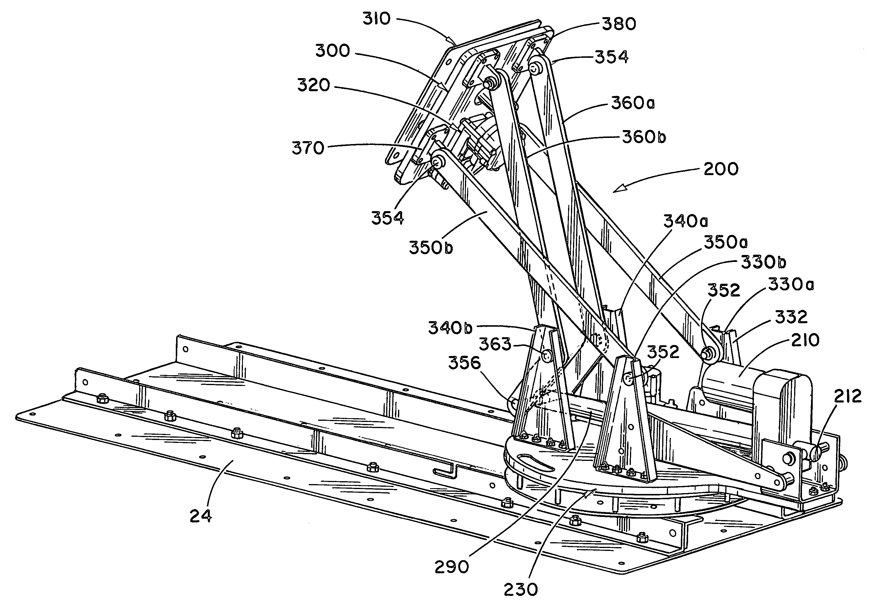
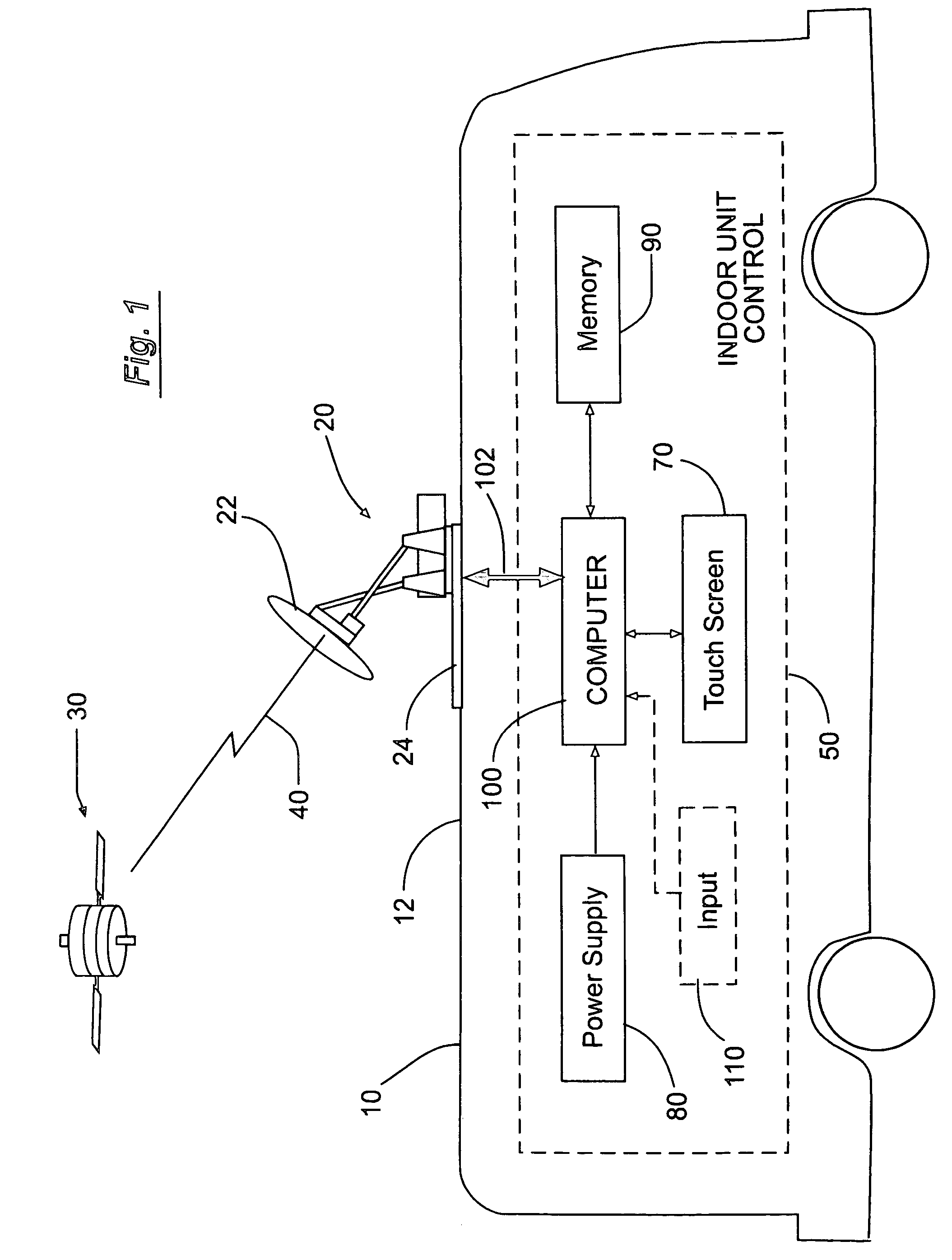
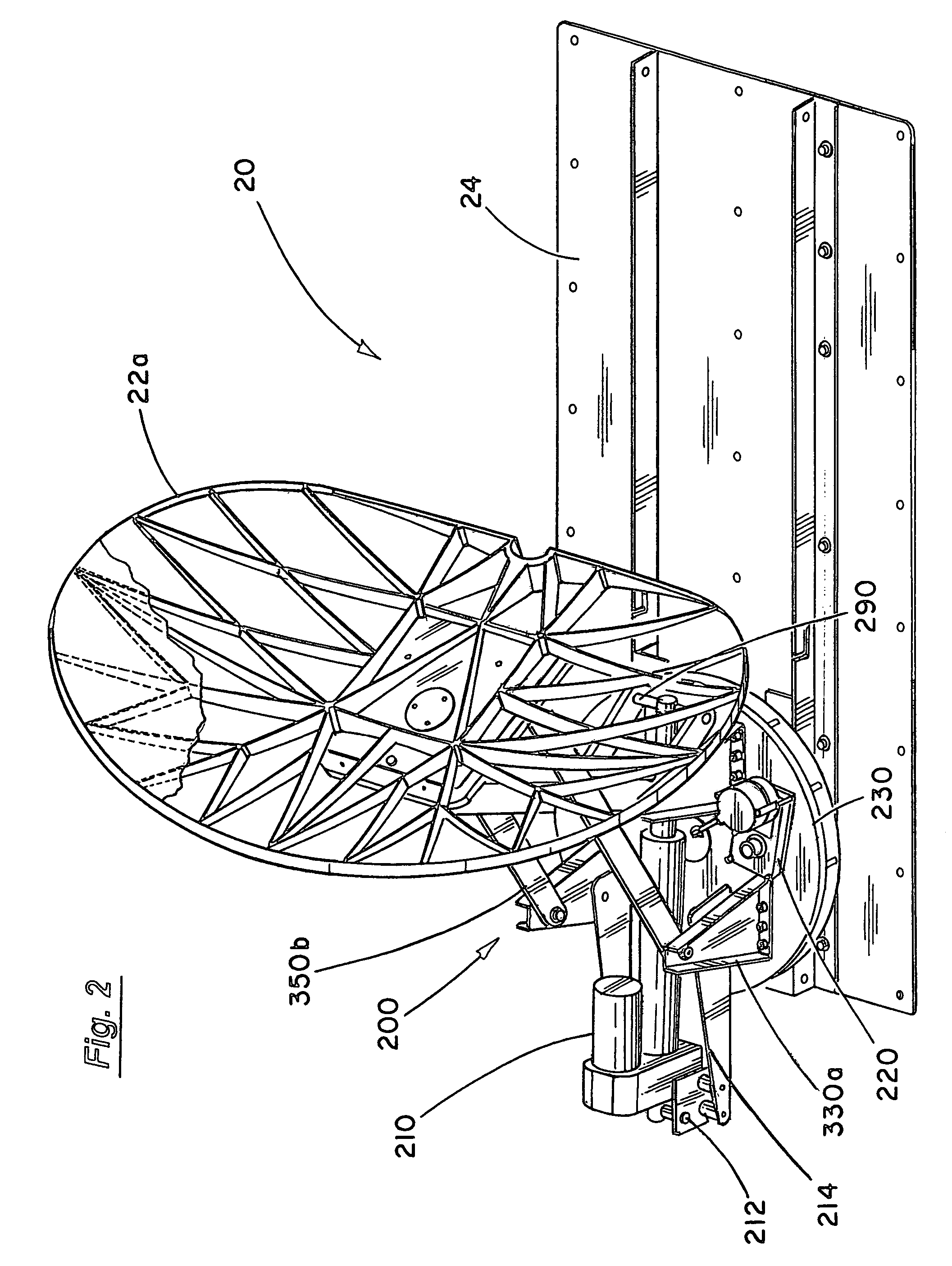
[0021]Overview of Use. In FIG. 1, a vehicle 10 is shown having a roof-mounted satellite antenna system 20 in communication with a satellite 30 to broadcast and receive signals 40. In the interior of the vehicle 10 is an indoor unit control 50 for controlling over cable(s) 102 the operation of the satellite antenna system 20 and the communication with the satellite 30. The indoor unit control 50 has a computer 100, a touch screen 70, and a power supply 80. These components are conventionally available and are suitably designed to work with other hardware interfaces and software controls to conventionally stow and deploy the dish antenna 22 of the satellite antenna system 20 that is mounted 24 to the roof 12 of the vehicle 10. The accompanying drawings illustrate a conventional dish antenna 22, but it should be understood that other types of satellite antennas could be used in the present invention.

[0022]It is to be understood that a number of different conventional indoor unit contro...


PUM


Abstract

An elevation mechanism for a satellite antenna system allows the antenna to be moved between a deployed position and a stowed position. The elevation mechanism includes a lift bar driven by a motor having one end pivotally connected to the back of the antenna and a pivot connection point pivotally connected to the base of the satellite antenna system. A tilt link bar has a first end pivotally connected to the back of the antenna and a second end pivotally connected to the base. The tilt link bar causes the antenna to pivot as the antenna moves between the stowed position and the deployed position so that in the stowed position the antenna faces downward.

Description

RELATED APPLICATION[0001]The present application is based on, and claims priority to the Applicant's U.S. Provisional Patent Application Ser. No. 60 / 601,362, entitled “Nomadic Storable Satellite Antenna System,” filed on Aug. 13, 2004.BACKGROUND OF THE INVENTION[0002]1. Field of the Invention[0003]The present invention relates to a mobile satellite antenna system mounted on the rooftop of a vehicle that can be quickly deployed and targeted on a satellite or stowed for transport.[0004]2. Prior Art[0005]The mobile satellite antenna market is growing due to the increased demand for high bandwidth communication between a vehicle and a satellite. For example, recreational vehicle users travel with laptop computers and desire high bandwidth access to the Internet. Commercial users such as those who are, for example, found in the oil and gas industry with mobile vehicles traveling from one location to another in the field have the same need.[0006]Some users of mobile satellite antennas req...

Claims


Application Information

Patent Timeline
Patent Type & Authority Patents(United States)
IPC IPC(8): H01Q1/32H01Q1/10
CPCH01Q1/325H01Q3/04
Inventor MCEWAN, GEORGE TYLER
Owner WINEGARD
Why Eureka
Try Eureka