Orthodontic bracket system comprising multiple brackets having multiple aligned slots

a technology of orthodontic brackets and slots, applied in dentistry, medical science, dental tools, etc., can solve the problems of difficulty in aligning both the main slot and the secondary or auxiliary slots that lie in a different plan

Inactive Publication Date: 2007-06-26
ABELS NORBERT +1
View PDF33 Cites 52 Cited by
  • Summary
  • Abstract
  • Description
  • Claims
  • Application Information

AI Technical Summary

Benefits of technology

[0010]The orthodontic bracket system of the present invention includes a plurality of orthodontic brackets, each bracket sized and configured to be placed on a particular tooth of a patient during an orthodontic treatment procedure. Each bracket includes at least two arch wire slots that lie in different planes. The arch wire slots are positioned relative to the bracket base so that when the patient's teeth have become properly aligned as a result of the orthodontic treatment procedure, the corresponding arch wire slots of all the brackets will be substantially aligned. This, in turn, allows for the continual use of arch wires that remain “straight” throughout the procedure (i.e., that have a “straight” or regular curvature with little or no abrupt or irregular bends).
[0013]Because of these variations in the size and angle of various teeth of the dental arch, the various brackets intended for placement on those teeth include arch wire slots oriented differently relative to the bonding surface of the bracket base. The arch wire slots of each orthodontic bracket are formed in the bracket base so that when the brackets are placed on the teeth of the dental arch the arch wire slots are substantially aligned once treatment is complete. When treatment is complete, the arch wire will be evenly and smoothly curved, without the need for any deviating bends (which are elaborate and difficult to form).

Problems solved by technology

Whereas aligning the main arch wire slot may be routine, aligning both the main slot and the secondary or auxiliary slots that lie in a different plane may be challenging because of varying tooth size and orientation in normally aligned teeth and corresponding variations in size and shape of brackets for each tooth.

Method used


Image

  • Orthodontic bracket system comprising multiple brackets having multiple aligned slots
  • Orthodontic bracket system comprising multiple brackets having multiple aligned slots
  • Orthodontic bracket system comprising multiple brackets having multiple aligned slots

Examples


Embodiment Construction

I. Introduction

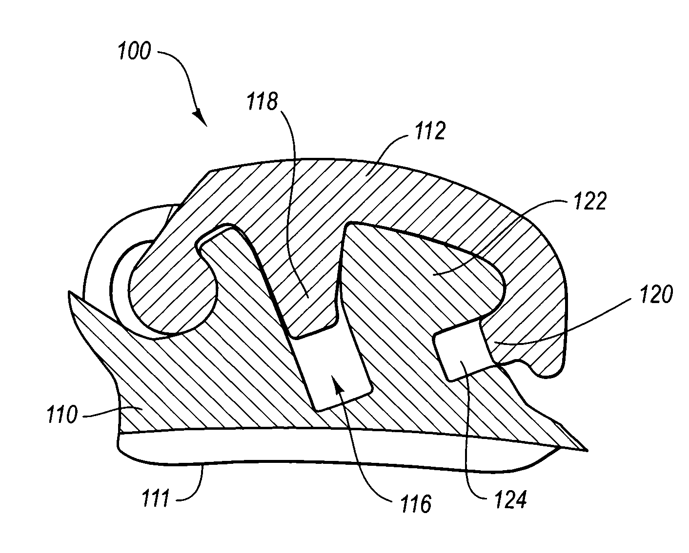
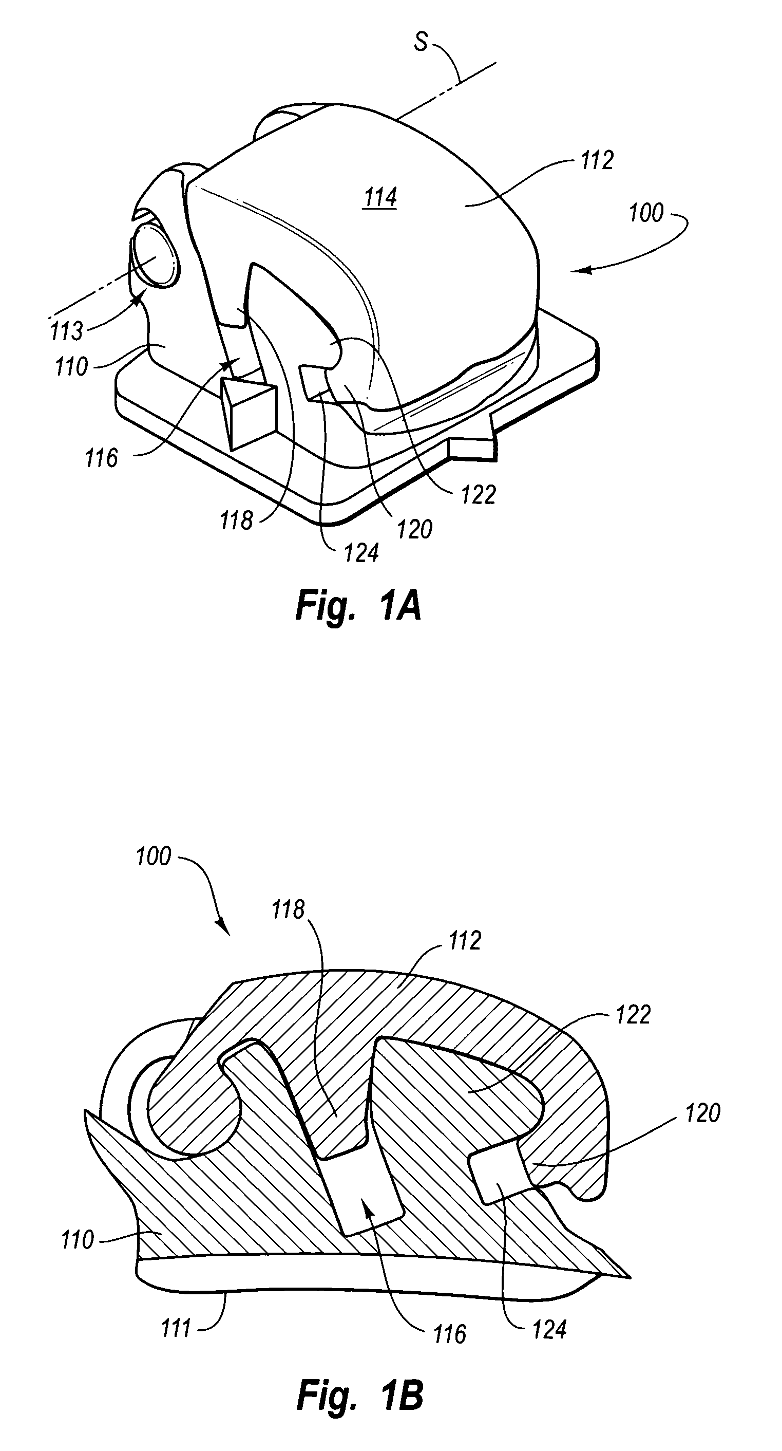
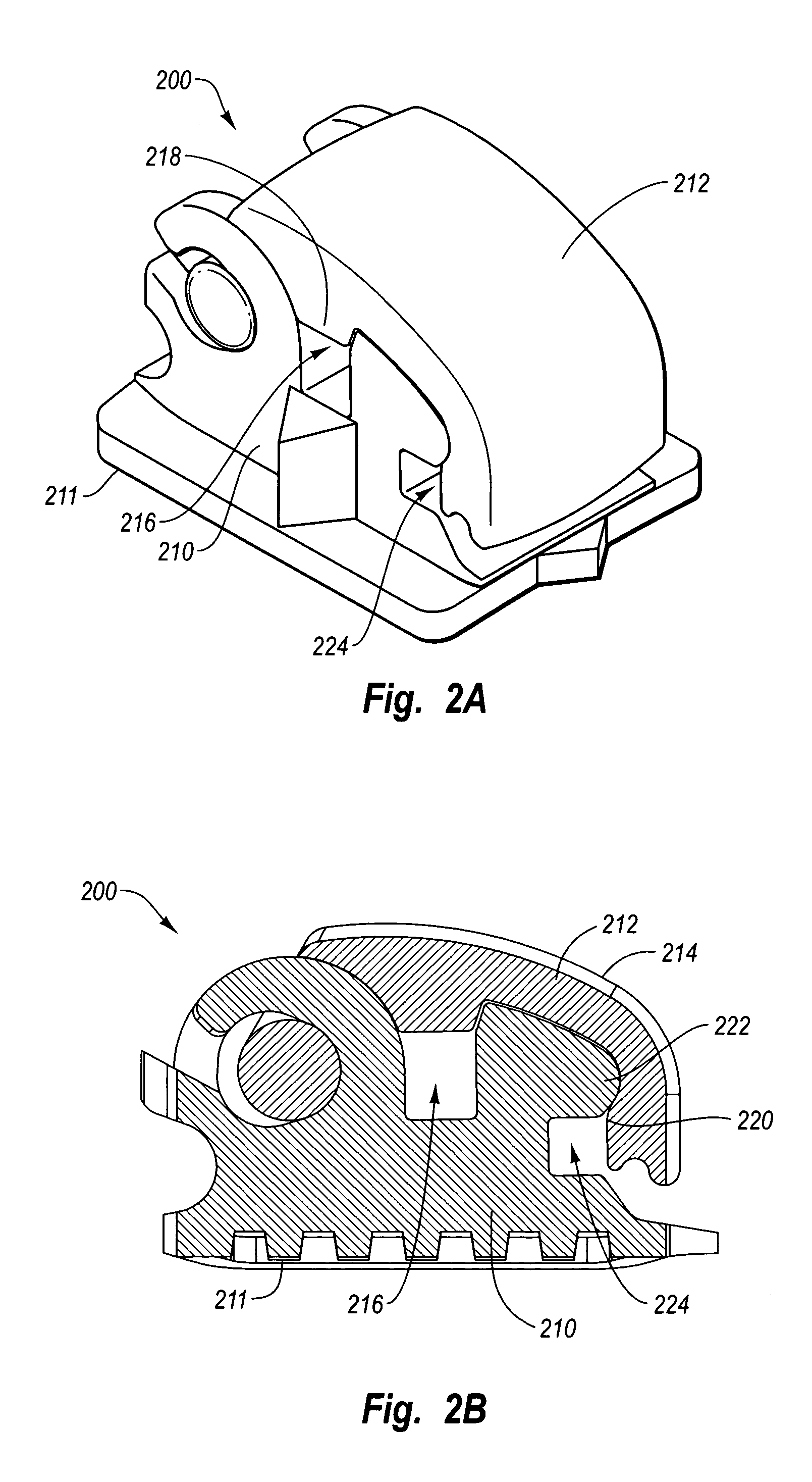
[0025]The orthodontic bracket system of the present invention includes a plurality of orthodontic brackets, each bracket sized and configured to be placed on a particular tooth of a patient during an orthodontic treatment procedure. Each bracket includes at least two arch wire slots that lie in different planes. The arch wire slots are positioned relative to the bracket base so that when the patient's teeth have become properly aligned as a result of the orthodontic procedure, the corresponding arch wire slots of all the brackets will be substantially aligned. In other words, the corresponding arch wire slots of all the brackets are aligned so that an arch wire engaged in the slots is “straight,” having little or no abrupt or irregular bends along the length of the arch wire.

[0026]The orthodontic brackets of the system may be configured for placement on either the upper or lower dental arch. For example, the system may include as few as two or as many as fourteen orth...


PUM


Abstract

An orthodontic bracket system includes a plurality of orthodontic brackets, each bracket sized and configured to be placed on a particular tooth of a patient during an orthodontic treatment procedure. Each bracket includes at least two arch wire slots that lie in different planes. The arch wire slots are positioned relative to the bracket base so that when the patient's teeth have become properly aligned as a result of the orthodontic procedure, the corresponding arch wire slots of all the brackets will be substantially aligned.

Description

BACKGROUND OF THE INVENTION[0001]1. The Field of the Invention[0002]The present invention relates to orthodontic brackets, more particularly to orthodontic bracket systems for use during orthodontic procedures.[0003]2. The Relevant Technology[0004]Orthodontics is a specialized field of dentistry that involves the application of mechanical forces to urge poorly positioned, or crooked, teeth into correct alignment and orientation. Orthodontic procedures can be used for cosmetic enhancement of teeth, as well as medically necessary movement of teeth to correct underbites or overbites. For example, orthodontic treatment can improve the patient's occlusion, or enhance spatial matching of corresponding teeth.[0005]The most common form of orthodontic treatment involves the use of orthodontic brackets and wires, which together are commonly referred to as “braces”. Orthodontic brackets, more particularly the orthodontic bases, are small slotted bodies configured for direct attachment to the p...

Claims


Application Information

Patent Timeline
Patent Type & Authority Patents(United States)
IPC IPC(8): A61C3/00A61C7/20A61C7/28
CPCA61C7/285
Inventor ABELS, NORBERTBACKES, CLAUS-H.
Owner ABELS NORBERT
Why Eureka
Try Eureka