Pleated shade with sewn in pleats

a pleat and shade technology, applied in the field of pleats, can solve problems such as difficulty in pleating

Inactive Publication Date: 2007-07-17
ITA
View PDF12 Cites 101 Cited by
  • Summary
  • Abstract
  • Description
  • Claims
  • Application Information

AI Technical Summary

Problems solved by technology

Furthermore, there are some materials such as lace which are difficult to pleat because the weave is so open that there is not enough material to retain pleat retention coatings.

Method used


Image

  • Pleated shade with sewn in pleats
  • Pleated shade with sewn in pleats
  • Pleated shade with sewn in pleats

Examples


Embodiment Construction

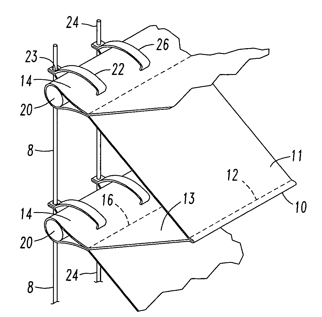
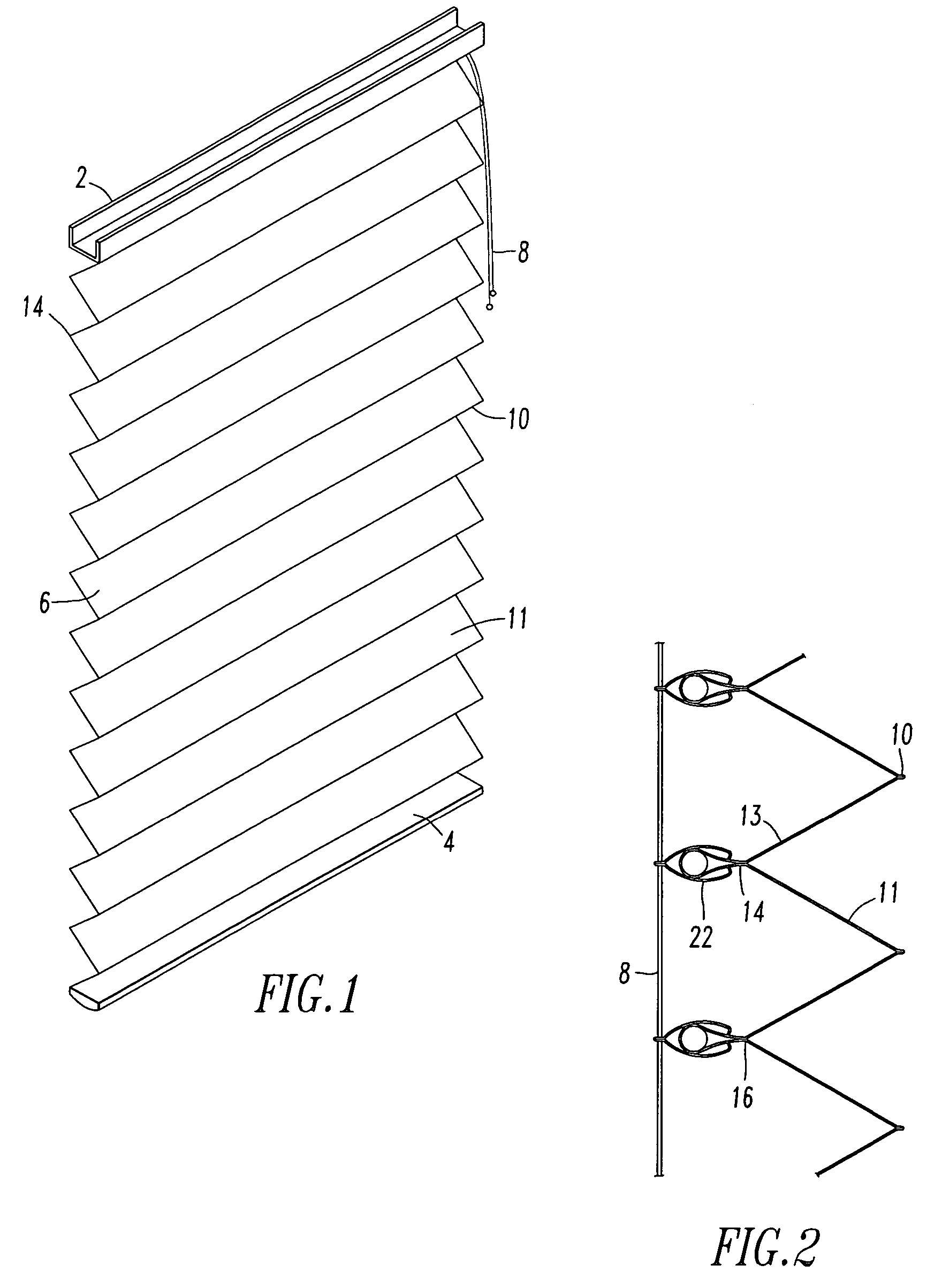
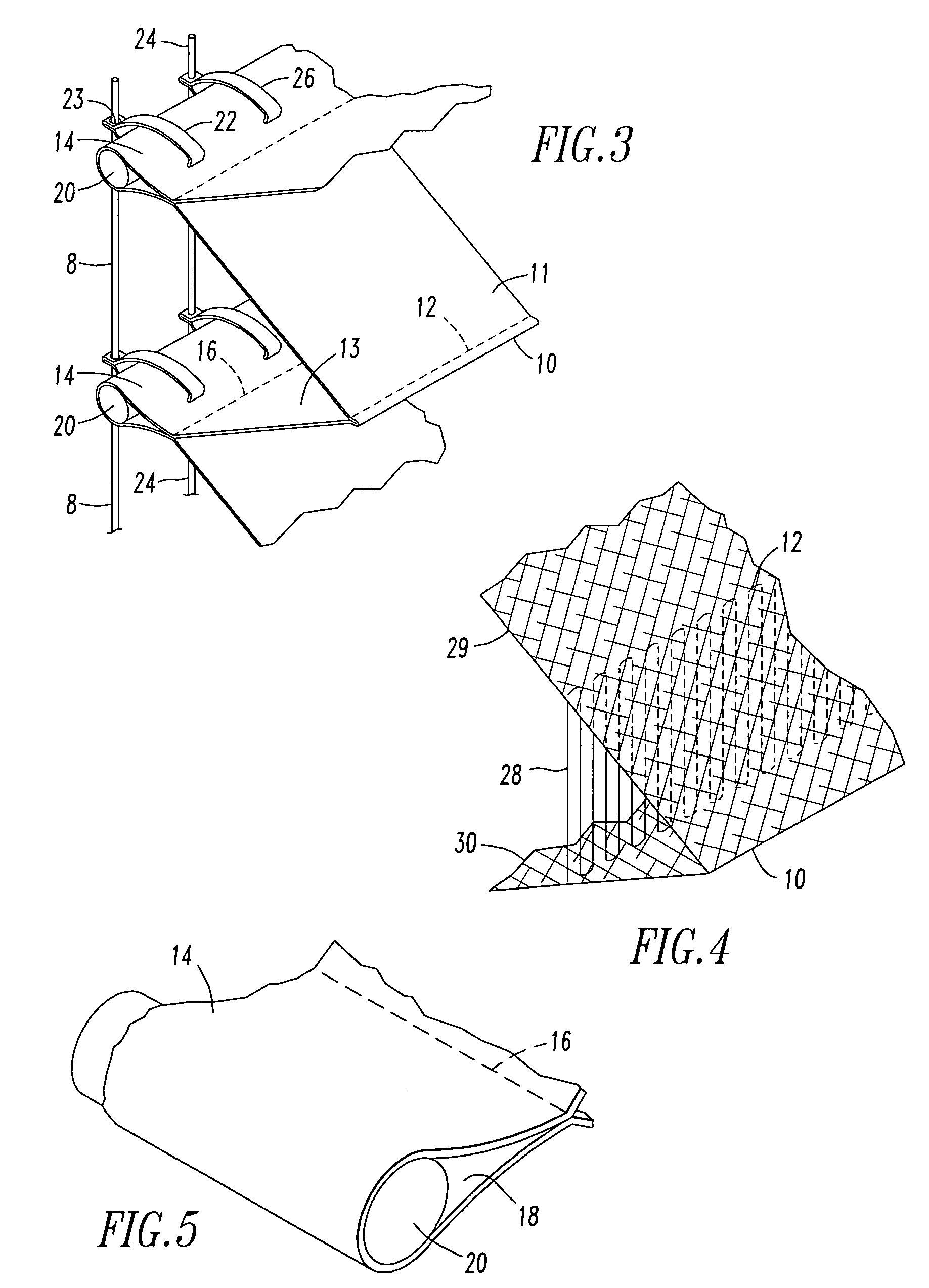
[0015]A first present preferred embodiment of my pleated shade with sewn in pleats, shown in FIGS. 1 through 5, has a panel of pleated material 6 extending between a headrail 2 and bottomrail 4. Lift cords 8 extend from the bottomrail into and through the headrail. As can be seen most clearly in FIGS. 2 and 3, a series of front pleats 10 extend outward from the front surface 11 of the panel of material 6. A front seam 12 is sewn into the panel of material 6 to form the front pleats. I prefer that the seam be positioned so that there is not more than one sixteenth of an inch of material between the seam and the fold at the outermost portion of the pleat. A tight seam may create a small tab of about one sixteenth of an inch or less that is imperceptible when the shade is viewed from a distance of at few feet. Such a small tab will appear to be a fold rather than a tab when the shade is hung on a window and seen from a distance. In many fabrics the number of threads within the small ta...


PUM


Abstract

A pleated shade with sewn in pleats is provided, in which each pleat is formed by a seam. Preferably, the seams that form pleats in the front side of the material separate only a few threads of the fabric from the main portions of the pleat. The seams that form pleats in the back surface of the panel preferably form a large tab of approximately one fourth of an inch which opens to create a pocket adjacent each seam. A stiff or flexible rod is placed in each pocket. Lift cords and spacer cords are attached to the larger rear tabs by clips.

Description

FIELD OF THE INVENTION[0001]This invention relates generally to a pleated shade, and more particularly to a pleated shade wherein some of the pleats have a tab.BACKGROUND OF THE INVENTION[0002]In a standard pleated shade construction, a piece of material having a front side and a back side is pleated into a plurality of horizontal sections which stack one on top of the other when the shade is in its raised position. Alternate pleats face toward the front side or the rear side of the shade. Each section has at least one hole punched preferably through the transverse center thereof which holes are aligned when the shade is folded. Normally, there would be two or more aligned rows of holes formed in the shade sections. Lift cords passing through the aligned holes are utilized to control the raising and lowering of the shade and also control the folding of the pleat.[0003]U.S. Pat. No. 4,974,656 discloses a pleated shade construction in which tabs are formed on the pleats on the rear of...

Claims


Application Information

Patent Timeline
Patent Type & Authority Patents(United States)
IPC IPC(8): A47H5/00
CPCE06B9/264
Inventor SIEGEL, LEONARD
Owner ITA
Why Eureka
Try Eureka