Cable or the like protection and guide device

a protection and guide device technology, applied in the direction of couplings, machine supports, relatively moving parts, etc., can solve the problems of easy vibration disengagement, serious failure of engagement, and difficulty in adjusting the position of the device, so as to reduce the effort of operation, the device is easy to disengage and disengage easily. , the effect of reliable engagement and disengagement of the opening/closing arm

Active Publication Date: 2007-07-31
TSUBAKIMOTO CHAIN CO
View PDF6 Cites 28 Cited by
  • Summary
  • Abstract
  • Description
  • Claims
  • Application Information

AI Technical Summary

Benefits of technology

[0015]The cable or the like protection and guide device of the invention includes a main locking mechanism which disengageably secures the opening / closing arm and the other link plate. An auxiliary locking mechanism also disengageably locks the opening / closing arm and the other link plate. The engagement between the opening / closing arm and the other link plate is performed by dual locking engagement mechanisms. A load, which acts on the opening / closing arm is distributed between both the main locking mechanism and the auxiliary locking mechanism. Excellent endurance of the device can be achieved. Additionally, even if the main locking mechanism is disengaged during operation the auxiliary mechanism is still engaged and inadvertent disengagement of the opening / closing arm during operation is avoided. As a result, reliable engagement and disengagement of the opening / closing arm can be realized. Additionally, the following peculiar effects can be obtained.
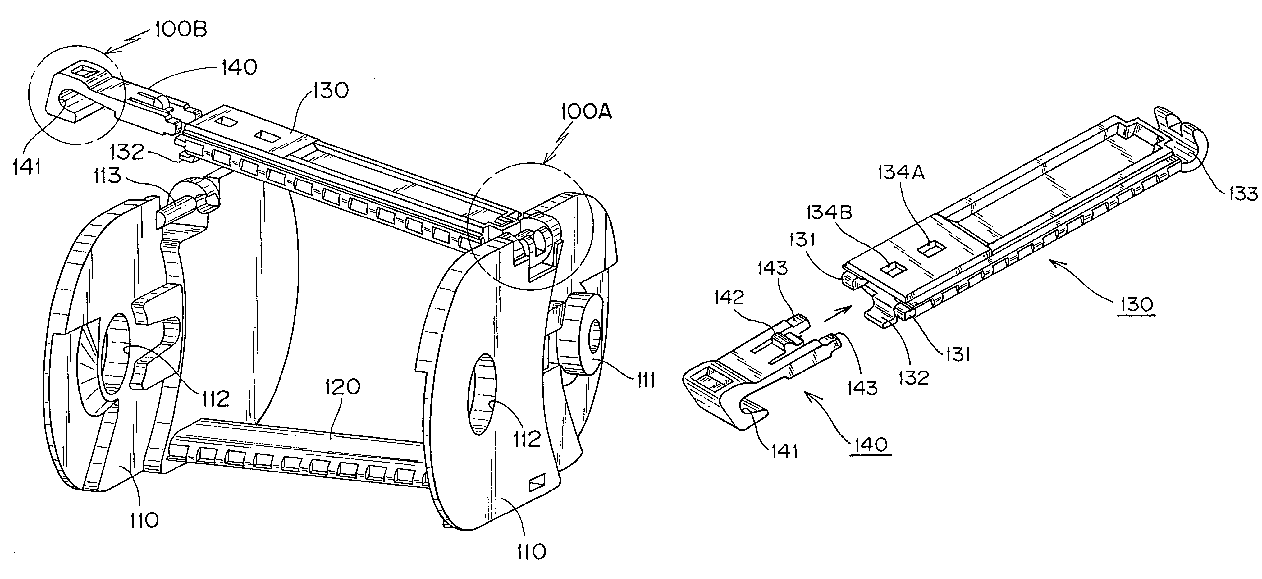
[0016]The main locking mechanism comprises an engagement pin and an engagement piece. The engagement pin is integrally molded in an upper portion of the other link plate and extends in the longitudinal direction of the chain. The engagement piece is slidably attached to the second end of the opening / closing arm and is movable from the outside toward the inside of the link plate along the opening / closing arm. The engagement piece when opened reveals an engagement pin insertion groove engageable with the engagement pin. The engagement piece moves in the direction of the opening / closing arm. The pivoting direction of the opening / closing arm and the direction of movement of the engagement piece are different from each other. Thus, as long as the engagement piece has engaged the engagement pin and the protrusion piece is inserted into the protrusion piece insertion groove, the opening / closing arm is not inadvertently disengaged from the link plate. Further, since the engagement pin insertion groove in the engagement piece is moved from the outside toward the inside of the link plate to engage with an engagement pin, the engagement operation for engagement securing the opening / closing arm to the link plate becomes easy and the efforts of operation can be reduced.
[0017]The auxiliary locking mechanism comprises a protrusion piece insertion groove and an auxiliary protrusion piece. The protrusion piece insertion groove is integrally molded in the other link plate and in the vicinity of an end portion of the engagement pin. The opening of the protrusion piece insertion groove faces the inside of the link plate. An auxiliary protrusion piece is integrally molded on the second end of the opening / closing arm and is engageably inserted into the protrusion piece insertion groove from the inside toward the outside of the other link plate. When the auxiliary protrusion piece is inserted into the protrusion piece insertion groove, sandwiching pressure from both right and left link plates acts on the auxiliary protrusion piece. Thus, an insertion state of the auxiliary protrusion piece into the protrusion piece insertion groove is reliable and stable. The strength of the auxiliary lock mechanism allows miniaturization to be attained without compromising the strength or endurance of the device. Further, even if the main locking mechanism does not work, the opening / closing arm does not disengage from the link plate and torsional rigidity of the entire link body is significantly improved.
[0018]Further, a guide surface is integrally formed in the vicinity of the end portion of the engagement pin. The guide surface positions the auxiliary protrusion piece for entry into the protrusion piece insertion groove. Force is applied to the opening / closing arm and the gap between the right and left link plates is widened. Or, put another way, the gap between the link plate and the other link plate is increased. The protrusion piece is guided along the guide surface which allows the auxiliary protrusion piece to slide into place within the protrusion piece insertion groove. As a result, the engagement operation load is reduced.
[0019]Further, a locking tongue piece cooperates with the engagement pin insertion groove in the engagement piece to hold the engagement pin. The locking tongue piece is integrally formed in the vicinity of the auxiliary protrusion piece. The opening / closing arm is reliably locked with an engagement pin so that the opportunity for inadvertent disengagement can be significantly reduced.
[0020]Additionally, the hinge connecting mechanism is comprised by a second engagement pin and an engagement pin insertion groove. The second engagement pin is integrally molded in an upper end portion on the link plate denoted one link plate and extends in the longitudinal direction of a chain. The engagement pin insertion groove formed on the second end of the engagement piece is open in the inner peripheral side thereof. The engagement pin insertion groove can be engaged with the second engagement pin when the auxiliary locking mechanism is engaged. The opening direction of the engagement pin insertion groove formed on the end of the engagement piece slidably attached to the opening / closing arm is different from the opening direction of the protrusion piece insertion groove of the auxiliary locking mechanism.

Problems solved by technology

As a result when both elements are not reliably fixed to a required engagement position due to insufficient positioning there are problems.
One serious problem that may occur is the easy disengagement by vibration or the like during operation.
This can lead to a serious failure in engagement.
Further, when members forming the engagement structure break, the other end of the opening / closing arm cannot be fixed to the upper end portion of the other link plate and the opening / closing arm is separated.
Further, when an upper end portion of the other link plate and the other end of an opening / closing arm are fixed to each other by only one engagement structure such as an engagement pin insertion groove in an engagement piece other problems may occur.
For example, when the cable (or the like) is heavy, the large load applied to the engagement structure can result in significant loss of endurance throughout the entire structure.
Further, there is a problem that the size of the engagement structure has limitations due to strength requirements.
As a result, miniaturization of the entire device with sufficient strength cannot be achieved.

Method used


Image

  • Cable or the like protection and guide device
  • Cable or the like protection and guide device
  • Cable or the like protection and guide device

Examples


example

[0035]A cable or the like protection and guide device, which is one example of the present invention, will be described with reference to drawings.

[0036]First, FIG. 1 is a schematic view of a cable or the like protection and guide device, which is one example of the present invention. FIG. 2 is an entire view of a link body shown in FIG. 1. FIG. 3 is a perspective view showing a connection state between link plates and a connecting arm. FIG. 4 is an exploded view of an opening / closing arm and an engagement piece. FIG. 5 is a perspective view showing a state where an opening / closing arm is locked by only an auxiliary locking mechanism. FIG. 6 is an enlarged perspective view showing a securing starting state of a main locking mechanism. FIG. 7 is an enlarged perspective view showing a securing completion state of the main locking mechanism. FIG. 8 is an enlarged perspective view showing a locking starting state of an auxiliary locking mechanism. FIG. 9 is an enlarged perspective view ...


PUM

PropertyMeasurementUnit
elastic deformableaaaaaaaaaa
flexibleaaaaaaaaaa
sizeaaaaaaaaaa

Abstract

The object of the instant invention is to provide a cable (or the like) protection and guide device in which inadvertent disengagement during operation can be avoided. Engagement between an opening / closing arm and link plates is accomplished by a dual mechanism locking structure. Easy engagement during use allows for excellent durability. The dual locking structure exhibits adequate strength even in smaller scale versions. The cable protection and guide device contains a plurality of link bodies with each link body comprises one link plate and another (110, 110). The link bodies are flexibly connected to each other. Each link body includes a connecting arm (120), an opening / closing arm (130), a hinge connection mechanism (100A), a main locking mechanism (100B), and an auxiliary locking mechanism (100C). A main locking mechanism (100B) secures the opening / closing arm (130) and the link plates (110, 110). An auxiliary locking mechanism (100C) locks the opening / closing arm (130) and the link plates (110, 110).

Description

TECHNICAL FIELD[0001]The present invention relates to a cable or the like protection and guide device which safely and reliably protects and guides a flexible body such as an electric cable or a hose which supplies a movable machine with energy. More specifically, the present invention relates to a cable or the like protection and guide device comprising a plurality of link bodies flexibly connected to each other. Each link body comprises one link plate and another link plate, a connecting plate, and an opening / closing arm. The connecting arm connects the respective lower edges of the link plates. The opening / closing arm is connected to the respective upper edges (upper portions) of the link plates.BACKGROUND TECHNOLOGY[0002]The cable or the like protection and guide device comprises link bodies flexibly connected to adjacent link bodies. The front end of each link body is flexibly connected to the respective rear end of an adjacent link body. One end of the cable or the like protec...

Claims


Application Information

Patent Timeline
Patent Type & Authority Patents(United States)
IPC IPC(8): F16G13/14H02G11/00
CPCF16G13/16H02G11/006Y10T403/1616Y10S59/90
Inventor KOMIYA, SHOICHIRO
Owner TSUBAKIMOTO CHAIN CO
Why Eureka
Try Eureka