Hook and method for separating wire harness using the same

a technology of wire harness and hook, which is applied in the direction of load-engaging elements, coupling device connections, electrical apparatus, etc., can solve the problems of inefficient transmission, tension load applied to the hook, and it takes a long time to separate the wire harness wh from the vehicle body, so as to achieve the effect of separating the wire harness from the vehicle body quickly and surely, and separating the wire harness using the hook

Inactive Publication Date: 2007-08-14
YAZAKI CORP
View PDF21 Cites 9 Cited by
  • Summary
  • Abstract
  • Description
  • Claims
  • Application Information

AI Technical Summary

Benefits of technology

[0014]The object of the present invention is to provide a hook capable of separating a wire harness from a vehicle body quickly and certainly and a method for separating the wire harness using the hook.
[0016]According to the present invention, a tension load is applied to a wire harness in a situation where the wire harness is sandwiched between a hook portion and a movable pressing portion. Therefore, a sideslip of a hook is certainly prevented, even if external force acts in an axial direction of the wire harness. As a result, the wire harness is quickly and certainly pulled out from a vehicle body.
[0018]According to the present invention, a tension load is applied to a wire harness in a situation where the wire harness is sandwiched between a hook portion and a movable pressing portion. Therefore, a sideslip of a hook is certainly prevented, even if external force acts in an axial direction of the wire harness. As a result, the wire harness is quickly and certainly pulled out from a vehicle body.

Problems solved by technology

Once the hook 50 sideslip on the wire harness WH, the tension load applied to the hook 50 is not efficiently transmitted to the wire harness WH, and accordingly it takes a lot of time to separate the wire harness WH from the vehicle body.
Once the wire harness WH slips through the hook 50, it is necessary to start a work for hooking the wire harness WH to the hook portion 52 from the beginning again, and accordingly it takes a lot of time and becomes complicated to separate the wire harness WH from the vehicle body.
However, since it is necessary to form the eye portions 70 on each wire harness WH′ mounted to the vehicle body, it becomes complicated and costs a lot of money to manufacture the wire harness WH′, and accordingly this is not practical for the method.

Method used


Image

  • Hook and method for separating wire harness using the same
  • Hook and method for separating wire harness using the same
  • Hook and method for separating wire harness using the same

Examples


first embodiment

[0030]As shown in FIG. 4, a hook 1 comprises pair of hook bodies 2, a pair of hook portions 3, a support pin 4, a movable pressing portion 5, a coil spring 6, an operating portion 7 and a link unit 8.

[0031]The hook bodies 2, 2 are formed of two plates disposed apart from each other, respectively. The hook portions 3, 3 are integrally fixed to lower ends of the hook bodies 2, 2 respectively. The movable pressing portion 5 is substantially formed of a straight elongated-shape and rotatably supported between the hook portions 3, 3 via the support pin 4 on a first end side thereof. The coil spring 6 has both ends engaged to the first end of the movable pressing portion 5 and a bar which is fixed between the hook portions 3, 3, respectively. The operating portion 7 is subject to a tension load F of a hoist (not shown in FIGS. 4 to 6) via a chain 20 of the hoist. The link unit 8 has both ends connected to the movable pressing portion 5 and the operating portion 7, respectively and transmi...

second embodiment

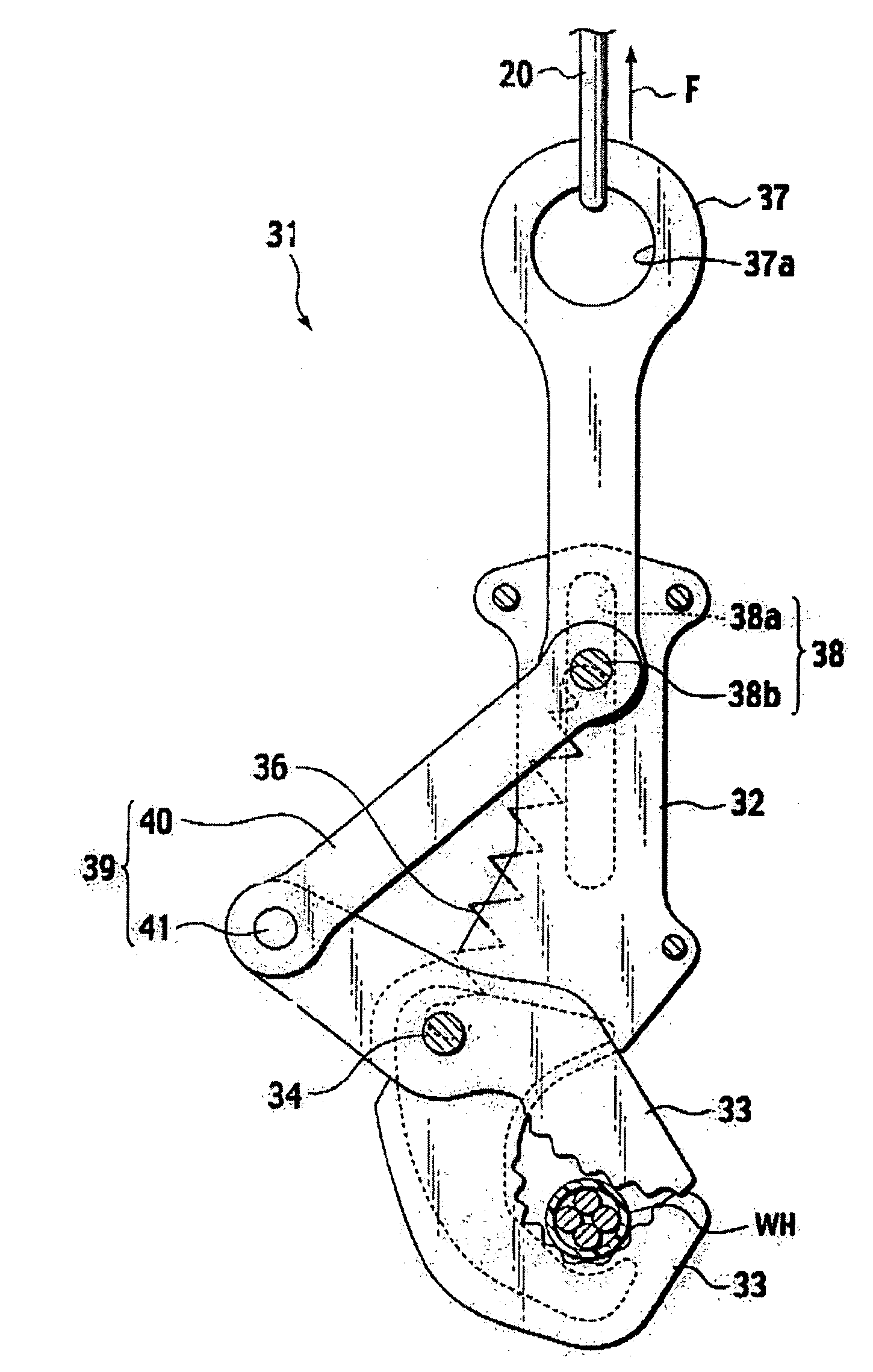
[0051]As shown in FIG. 7, a hook 31 comprises a pair of hook bodies 32, a pair of hook portions 33, a support pin 34, a movable pressing portion 35, a pair of coil springs 36 (one of the pair of coil springs 36 is shown in FIG. 7), an operating portion 37, a pair of guide members 38 (one of the pair of guide members 38 is shown in FIG. 7) and a link unit 39.

[0052]The hook bodies 32, 32 are formed of two plates disposed apart from each other, respectively. The hook portions 33, 33 are integrally fixed to lower ends of the hook bodies 32, 32 respectively. The movable pressing portion 35 is substantially formed of a straight elongated-shape and rotatably supported between the hook portions 33, 33 via the support pin 34 at a central part thereof. Each of the coil springs 36, 36 has both ends engaged to the support pin 34 and the guide member 38, respectively. The operating portion 37 is subject to a tension load F of a hoist (not shown in FIGS. 7 to 9) via a chain 20 of the hoist. The g...


PUM


Abstract

A hook comprises a pair of hook bodies, a pair of hook portions, a movable pressing portion, an operating portion and a link unit. The hook bodies are formed of two plates disposed apart from each other, respectively. The hook portions are integrally fixed to lower ends of the hook bodies, respectively. The movable pressing portion is rotatably supported between the hook portions. The operating portion is subject to a tension load of a hoist. The link unit has one end rotatably connected to the movable pressing portion and another end rotatably connected to the operating portion. When the operating portion is pulled upward, the movable pressing portion presses a wire harness, which is hooked to the hook portion, against the hook portion.

Description

CROSS REFERENCE TO RELATED APPLICATION[0001]This application claims benefit of priority under 35 U.S.C. § 119 to Japanese Patent Application No. 2003-430701, filed on Dec. 25, 2003 and Japanese Patent Application No. 2003-430708, filed on Dec. 25, 2003, the entire contents of which are incorporated by reference herein.BACKGROUND OF THE INVENTION[0002]1. Field of the Invention[0003]The present invention relates to a hook employed to separate a wire harness from a vehicle body and to a method for separating the wire harness using the same.[0004]2. Description of the Related Art[0005]In handling of disused automobiles, a hook employed to separate a wire harness from a vehicle body is conventionally disclosed in Japanese Patent Publication No. 2833674.[0006]As shown in FIGS. 1 and 2, a hook 50 comprises a hook body 51, a hook portion 52, a support pin 53, an operating portion 54, a rod member 55 and a lock member 56. The U-shaped hook portion 52 to which a wire harness WH is hooked is i...

Claims


Application Information

Patent Timeline
Patent Type & Authority Patents(United States)
IPC IPC(8): B66C1/48B66C1/36B66C1/38
CPCB66C1/36
Inventor KOMIZO, KENICHIROARAI, HIROAKISHIN, KATSUHIRONAGOSHI, TAKEFUMITSUYAMA, HATSUO
Owner YAZAKI CORP
Why Eureka
Try Eureka