Apparatus and method for monitoring transmission systems using embedded test signals

a transmission system and test signal technology, applied in the field of radio frequency transmission systems, can solve the problems of transmission system damage transmission line deterioration, etc., and achieve the effect of preventing transmission system damage, and preventing transmission system deterioration

Inactive Publication Date: 2007-11-20
SPX CORP
View PDF27 Cites 5 Cited by
  • Summary
  • Abstract
  • Description
  • Claims
  • Application Information

AI Technical Summary

Problems solved by technology

A disadvantage of systems in current use is that a waveguide or coaxial transmission system consisting of a transmission line and a load device can deteriorate gradually due to its exposure to a number of destructive factors, while the deterioration can continue undetected in normal use until a catastrophic failure reveals one or more problems.
Destructive factors likely to contribute to harm to transmission systems over periods of months or years can include, as examples, galvanic corrosion; cold flow under bolts caused by repeated temperature swings; metal fatigue associated with repeated mechanical stress cycling; exposure to chemically reactive pollutants; exposure to airborne salt; exposure to water condensed inside the transmission system due to temporary loss of pressurization or dehumidification; and hidden workmanship errors such as pinched O-rings or pinhole flaws in the materials from which the transmission system is constructed.
These and many other factors can lead to significant increases in voltage standing wave ratio (VSWR) at a point, high voltage breakdown, and other faults demanding immediate attention.
VSWR increases stemming from such destructive events can manifest suddenly due to events such as storm stress on deteriorated materials, or can manifest gradually in the form of cumulative degradation in performance over a protracted period.
Both problem modalities can require extensive efforts simply to identify and localize a single-point failure even after it has occurred.
Multiple-point degradations can likewise become established, requiring prolonged and potentially ineffective troubleshooting.
A typical operator response to prevent some types of severe functional faults from continuing to grow worse is prompt decrease in output power, resulting in loss of reception for the furthest customers and degraded reception for those nearer.
Even this response is not diagnostic, so it is still necessary to identify the failure that caused the system fault.
A time consuming diagnostic procedure can ensue, leading to the development of a corrective action plan, which may involve shutting down a multi-channel broadcast facility for an extended period during prime viewing hours, switching over to a reduced-performance backup system for an indefinite servicing period, or another method, any of which can potentially entail significant contract violations and incur financial penalties.
While the Ghost Cancellation Reference signal (GCR) is available for use in receivers, no methodology has been established for incorporating GCR into a high-power NTSC RF broadcast transmission system for real-time analysis of the state of health of the transmission system.
Similarly, no existing system has been established for realtime testing of non-broadcast applications.

Method used


Image

  • Apparatus and method for monitoring transmission systems using embedded test signals
  • Apparatus and method for monitoring transmission systems using embedded test signals
  • Apparatus and method for monitoring transmission systems using embedded test signals

Examples


Embodiment Construction

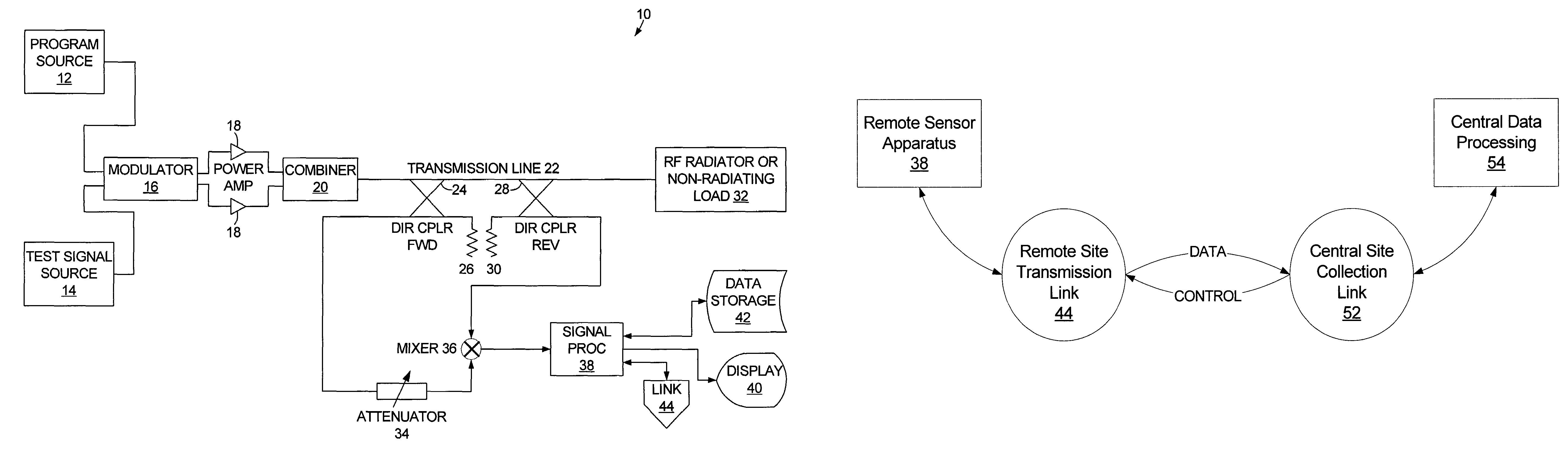
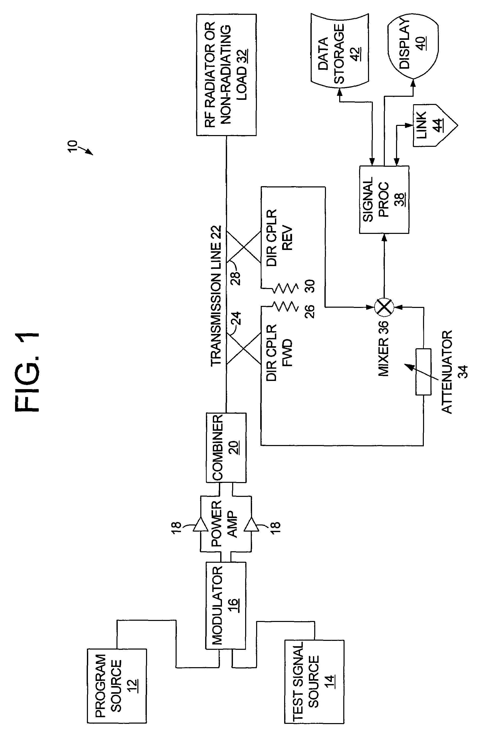
[0019]In accordance with some embodiments, the present invention provides a detective and diagnostic apparatus and method that can be applied continuously to provide prompt detection of degradation taking place in an RF transmission system, to include identification of the locus of each of an indefinite number of incipient failures.

[0020]In accordance with some embodiments of the invention, a sensing apparatus detects the fine detail of radio frequency (RF) reflections from a transmission system due to the impingement of a transmitted RF test signal embedded in the program content of a transmitted channel. The signal can be used to measure some of the characteristics of an RF signal transmission system. Some of the characteristics of the transmission system can be recorded, and measurements taken at any subsequent time, such as minutes, hours, months or years later, can be compared to the original recordings to detect gradual changes in the propagation capability of the system, with...


PUM


Abstract

A monitoring system for an RF transmission system, such as a multi-channel television broadcasting antenna feed system, gathers data about the physical and electrical condition of the RF transmission system in real time. The system can detect and localize deterioration and other time-dependent faults in the transmission system by the tendency of faults to produce reflections back to the transmitter that were not part of the original characterization of the installation. Some kinds of faults, identified early enough, can be corrected without replacing components, and especially without shutting down the transmission system during prime viewing hours in the case of television broadcasters, or during a critical period of use of the system in the case of other user types. Other faults can be detected in time to order replacement parts before the underlying problem becomes severe, and to allow servicing during periods of low demand.

Description

FIELD OF THE INVENTION[0001]The present invention relates generally to radio frequency transmission systems. More particularly, the invention relates to continuous monitoring of the condition of transmission systems.BACKGROUND OF THE INVENTION[0002]It is known in radio frequency systems to use a coaxial or waveguide transmission system to propagate radio frequency (RF) signals from place to place, such as from a broadcast transmitter to a broadcast antenna.[0003]A disadvantage of systems in current use is that a waveguide or coaxial transmission system consisting of a transmission line and a load device can deteriorate gradually due to its exposure to a number of destructive factors, while the deterioration can continue undetected in normal use until a catastrophic failure reveals one or more problems. Since a transmission system may be used, for example, for broadcast of several television channels using a shared, broad-band antenna system, it is possible for a multiplicity of chan...

Claims


Application Information

Patent Timeline
Patent Type & Authority Patents(United States)
IPC IPC(8): H04N1/00H03C1/62H04B17/00H04B3/46H04N17/00H04N17/02H04N5/00H04N5/38H04N7/00G01R31/11
CPCH04N17/00H04B17/0085H04B3/46G01R31/11
Inventor BROWN, JEFFREY M.SKALINA, ANDRE J.
Owner SPX CORP
Why Eureka
Try Eureka