System and method for smart system control for flowing fluid conditioners

a technology of smart system control and flowing fluid, which is applied in the direction of fluid couplings, rotary clutches, instruments, etc., can solve the problems of temperature directly affecting the performance of an internal combustion engine, operation problems, and catastrophic failures, so as to increase the fuel, reduce the boost level, and improve the effect of fuel

Inactive Publication Date: 2007-01-04
PERKINS MICHAEL T
View PDF17 Cites 27 Cited by
  • Summary
  • Abstract
  • Description
  • Claims
  • Application Information

AI Technical Summary

Benefits of technology

[0027] When the SSCFFC invention detects combustion problems it will exert control to provide conditioning or other means to counteract the abnormal combustion. For example, it may provide situation resolution with temperature reduction of fuel-air charge mixture. In the event this solution is ineffective, SSCFFC invention may increase fuel (in opposition i.e. if detonation is occurring fuel will be added prior to sparking, if pre-ignition is occurring fuel will be added subsequent to sparking), or boost level can be reduced (for example with electrically

Problems solved by technology

A small variation in temperature (above or below optimal) can cause operational problems at best and even catastrophic failures in some cases.
Temperature directly affects the performance of an internal combustion engine.
Air charge temperature also affects wear and reliability of engine components.
That is, requiring operation of the Peltier Junctions in a steady-state condition would be prohibitively power demanding.
Also, use in a strictly manual fashion during vehicle driving is not practical.
Without adequate strategic controls, the existing intercooler inventions will achieve no net benefits in real world (non-performance competition) applications.
Despite technological advances with intercoolers, several critical weaknesses remain in all prior systems.
Prior art does not provide for handling large temperature gains in the charged air by virtue of being air-to-air based intercoolers (these designs can not achieve wide temperature differentials due to the heat sink temperature always at or above ambient temperature).
Of the active systems, prior art runs the t

Method used


Image

  • System and method for smart system control for flowing fluid conditioners
  • System and method for smart system control for flowing fluid conditioners
  • System and method for smart system control for flowing fluid conditioners

Examples


Embodiment Construction

[0043] Reference will now be made to the drawings wherein like structures will be provided with like reference designations.

Hardware Overview of the Preferred Embodiment

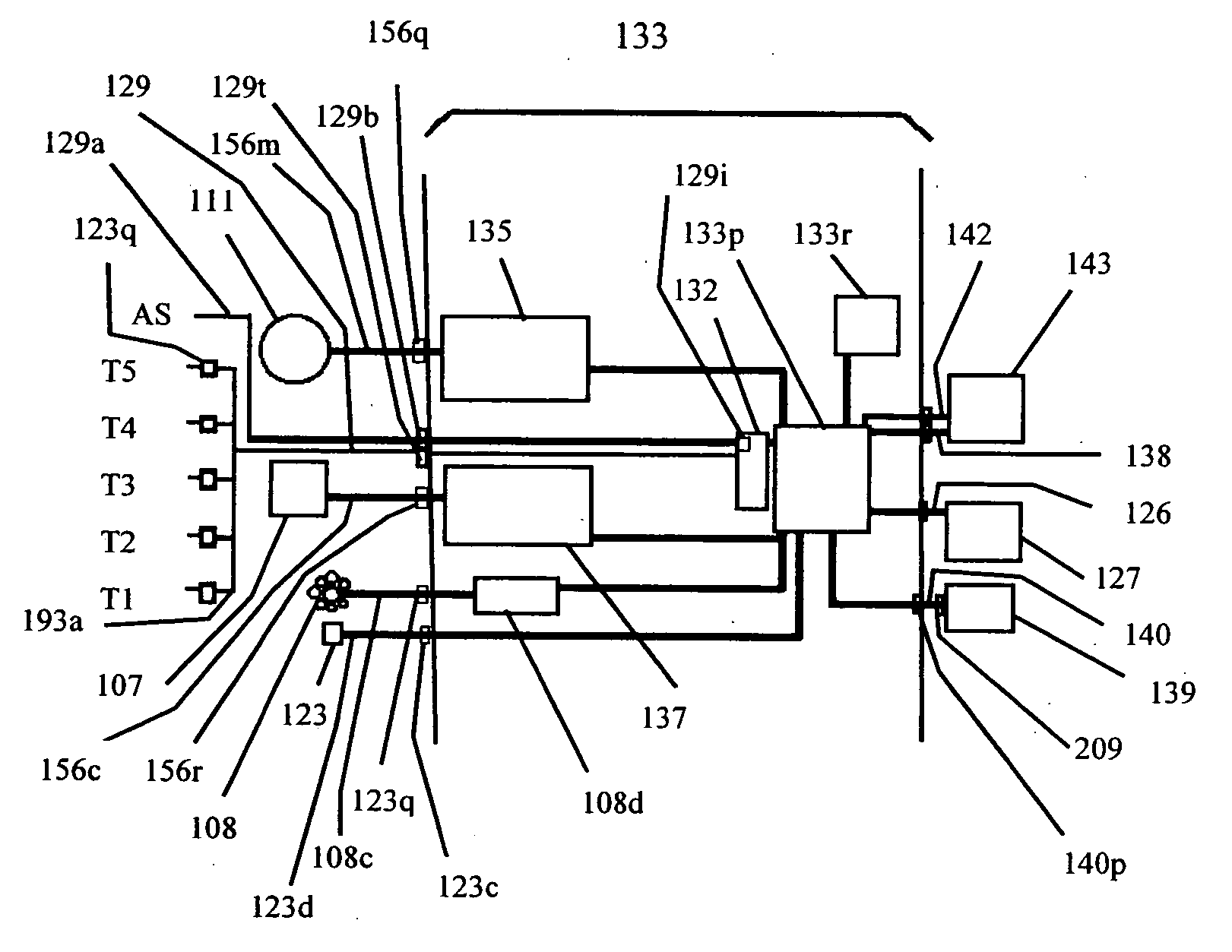
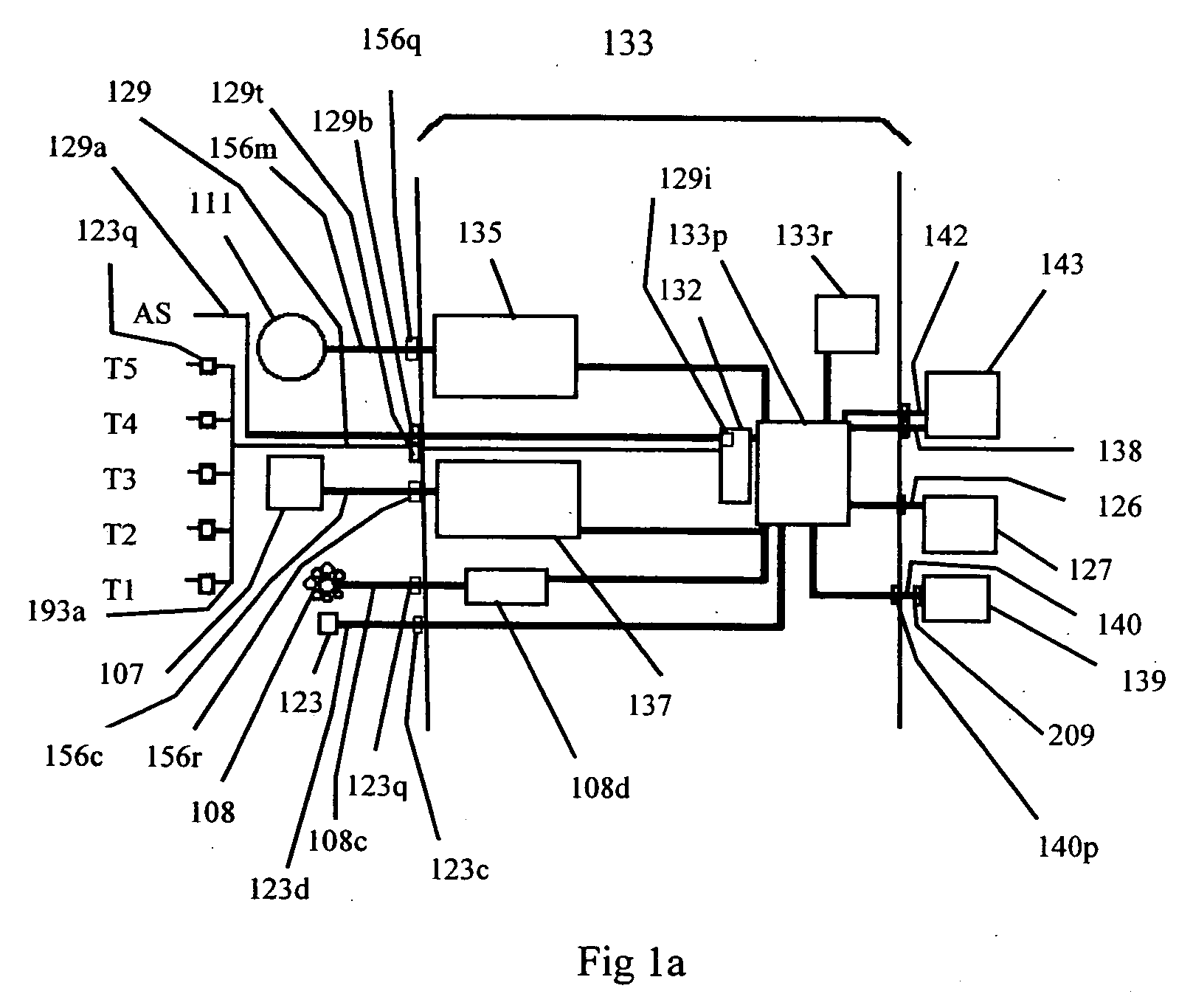
[0044]FIG. 1a discloses a block diagram of the SSCFFC with details of the controller 133. The heart of controller 133 is a DSP processor 133p. The processor 133p is a multi-function processor with sensing, processing and controlling capabilities such as a PIC 16F877 from Microchip Technology (www.microchip.com). The processor 133p monitors system components and receives system data inputs, and uses software to combine this information with resident tables from previous operations and host vehicle operating specifications, and executes system control functions. A real time clock 133r provides timing and synchronization capabilities. The controller 133 is housed in rugged plastic enclosure KS 1423 from Rittal company (www.rittal.co.uk). A sensor interface 132 is provided for amplification and conversion of sensor si...


PUM


Abstract

A method and system for temperature and boost control of engine intake air by use of an active conditioner control unit, which regulates relative amounts of electric current to at least one active conditioning device and an electrically driven booster motor. In one preferred embodiment it controls valves which optimally direct the path of airflow through a plurality of thermal conditioner storage chambers in response to signals from engine load level, temperature, and other sensors in order to optimally provide temperature conditioned air to the engine. This embodiment of the invention features immediate and efficient provision of conditioned and pressurized airflow to an internal combustion engine and removes parasitic power drains during low demand situations. This invention enhances cold start performance and operation with a pre-start thermal conditioner with warming capabilities. System increases flexibility for stationary operation and traffic restraints by supplementing heat sink transfers. System sensor array with advanced sensors monitoring combustion parameters to safely facilitate additional power output from host engines.

Description

FEDERALLY SPONSORED RESEARCH [0001] Not Applicable SEQUENCE LISTING OR PROGRAM [0002] Not Applicable BACKGROUND [0003] 1. Technical Field of Invention [0004] This invention relates to systems and methods for maximizing engine power output through the use of smart controllers for active conditioners and pressurizers of incoming air. The Smart System Controller for Flowing Fluid Conditioners (SSCFFC) invention is specifically for monitoring and control of the pressure boosting, cooling and heating of said incoming air in applications that require environmental flexibility and on-demand efficiency enhancement capability. [0005] 2. Description of Prior Art [0006] The trend toward smaller automobile engines is driven by a need to meet targets for lower carbon dioxide and other emissions. In order to achieve this goal, the auto industry is introducing smaller engines that are more fuel-efficient, but customers have come to expect a high level of performance. Designers are able to choose f...

Claims


Application Information

Patent Timeline
IPC IPC(8): B60T17/00
CPCB60T1/10F02B29/0418F02B29/0481Y02T10/166F02B33/443Y02T10/146F02B29/0493Y02T10/12
Inventor PERKINS, MICHAEL T.
Owner PERKINS MICHAEL T
Why Eureka
Try Eureka