
Variable system of internal combustion engine and method for controlling the same

a variable system and internal combustion engine technology, applied in combustion engines, electrical control, valve arrangements, etc., can solve the problems of reducing thermal efficiency, mechanical expansion ratio, mechanical compression ratio, etc., to reduce the effective compression ratio, improve thermal efficiency, and enhance knocking resistance capability

Inactive Publication Date: 2019-09-19
HITACHI AUTOMOTIVE SYST LTD
View PDF12 Cites 2 Cited by
  • Summary
  • Abstract
  • Description
  • Claims
  • Application Information

AI Technical Summary

Benefits of technology

The present invention proposes a variable system for internal combustion engines that can prevent or reduce thermal damage on exhaust-system components and improve fuel economy when the engine torque reaches the maximum level. This is achieved by reducing the mechanical compression ratio and increasing the mechanical expansion ratio to decrease the temperature of the exhaust gas and improve thermal efficiency. Overall, this system offers a solution to improve performance and fuel economy of high-output engines while minimizing the risk of damage to the exhaust system.

Problems solved by technology

However, this method can improve the knocking resistance capability, but, on the other hand, also leads to a reduction in a mechanical expansion ratio along with the reduction in the mechanical compression ratio, thereby newly raising a problem of facilitating occurrence of thermal damage on an exhaust-system component (an exhaust pipe, a catalyst for purifying exhaust gas, and the like) around the maximum engine torque (load) because a temperature of the exhaust gas also increases, as well as thermal efficiency reduces and thus the fuel economy is deteriorated.

Method used


Image

  • Variable system of internal combustion engine and method for controlling the same
  • Variable system of internal combustion engine and method for controlling the same
  • Variable system of internal combustion engine and method for controlling the same

Examples


first embodiment

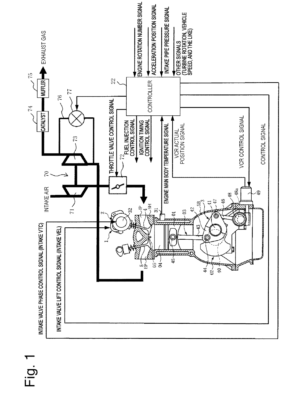
[0025]A variable system of an internal combustion engine according to a first embodiment of the present invention will be described, and FIG. 1 illustrates an overall configuration of the variable system of the internal combustion engine to which the present invention is applied.

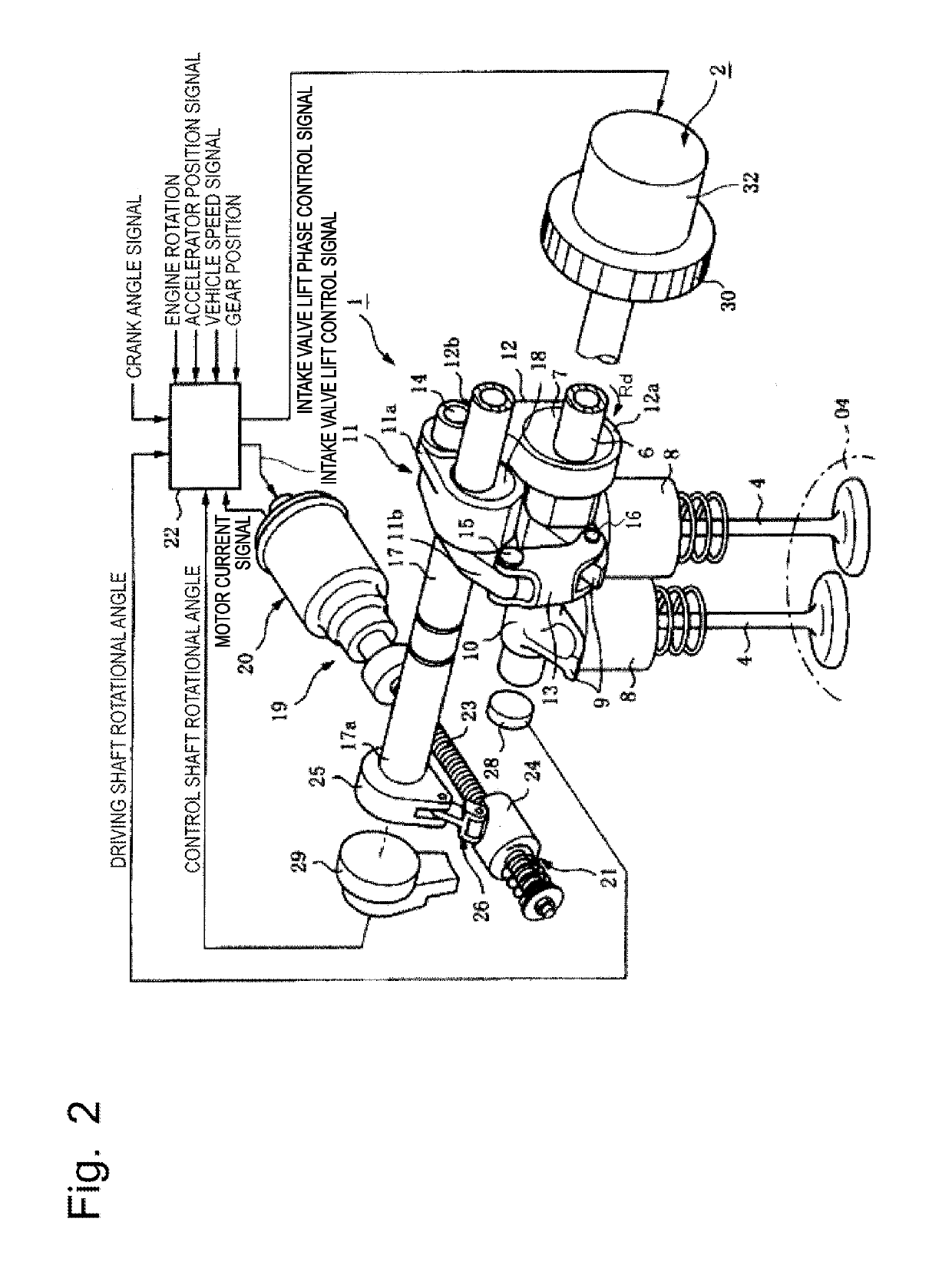
[0026]First, a basic configuration of the variable system of the internal combustion engine will be described with reference to FIG. 1. The variable system of the internal combustion engine includes a piston 01, an intake port IP and an exhaust port EP, and a pair of intake valve 4 and exhaust valve 5 for each one of cylinders. The piston 01 is provided vertically slidably due to, for example, a combustion pressure in a cylinder bore formed in a cylinder block SB. The intake port IP and the exhaust port EP are each formed inside a cylinder head SH. The pair of intake valve 4 and exhaust valve 5 is provided slidably in the cylinder head SH, and opens and closes opening ends of the intake and exhaust ports IP ...

second embodiment

[0092]Next, a second embodiment of the present invention will be described with reference to FIG. 9. The above-described embodiment proposes the method that controls the waste gate valve 73 to close it when the engine torque reaches the maximum engine torque Td set to guarantee the durability of the driving system. The present embodiment is different therefrom in terms of controlling the waste gate valve 77 to open it around the maximum engine torque Td. Further, the present embodiment is different from the first embodiment in terms of closing the intake valve at the closing timing IVC that is not the closing timing IVCd on the retard-angle side but is a closing timing IVCdad on the advance-angle side at the maximum engine torque Td. The closing timing IVCdad has approximately the same characteristic as the closing timing IVCa in the low load region.

[0093]Now, the closing timing IVC of the intake valve at the maximum engine torque Td is set to the retard-angle side as seen in the fi...

third embodiment

[0106]The second embodiment proposes the example of a so-called “early-closing Miller cycle”, which reduces the pump loss by advancing the closing timing IVC from the intake bottom dead center BDC with respect to the closing timings IVCa to IVCb of the intake valve in the low load region.

[0107]On the other hand, the third embodiment proposes an example of a so-called “late-closing Miller cycle”, which reduces the pump loss by retarding the closing timing IVC from the intake bottom dead center BDC as indicated by the closing timing IVCd similarly to the first embodiment even in the low load region, and an example of a different variable actuation valve configuration from the first embodiment. The present embodiment employing this “late-closing Miller cycle” will be described with reference to FIGS. 10(a) to 10(d).

[0108]The lift characteristic is controlled with use of the first variable actuation valve mechanism 1 in the first embodiment, but the lift amount characteristic of the int...


PUM


Abstract

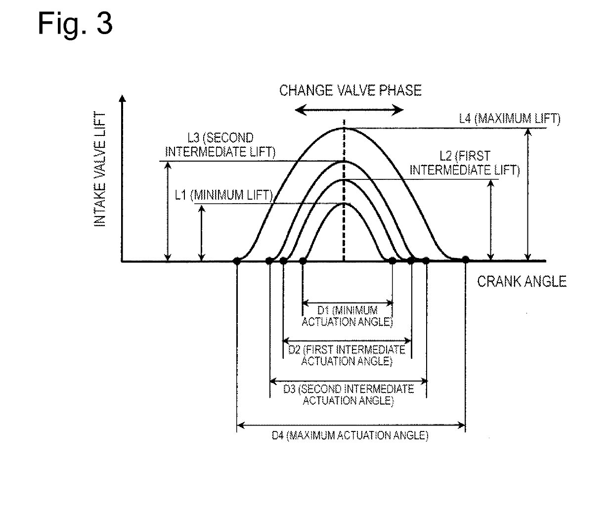
A variable system of an internal combustion engine spaces a closing timing IVC of an intake valve apart from an intake bottom dead center BDC by a variable actuation valve mechanism and also increases a mechanical expansion ratio εE by a variable compression ratio mechanism when an engine torque increases to around a maximum engine torque. The variable system sets the closing timing IVC of the intake valve to a closing timing IVCd spaced apart from the intake bottom dead center BDC around the maximum engine torque. Due to this control, the variable system can reduce an effective compression ratio to enhance a knocking resistance capability, and, further, achieve improvement of thermal efficiency and also reduce a temperature of exhaust gas to prevent or reduce thermal damage on an exhaust-system component by increasing the mechanical expansion ratio.

Description

TECHNICAL FIELD[0001]The present invention relates to a variable system of an internal combustion engine, in particular, to a variable system of an internal combustion engine including a variable compression ratio mechanism that controls a mechanical compression ratio in a four-cycle internal combustion engine and a variable actuation valve mechanism that controls a valve timing, and a method for controlling the variable system of the internal combustion engine.BACKGROUND ART[0002]For internal combustion engines relating to this kind of field, there is proposed improving an operational performance of the internal combustion engine by combining a variable compression ratio mechanism that variably controls a geometric compression ratio, i.e., a mechanical compression ratio of the internal combustion engine, and a variable actuation valve mechanism that variably controls opening / closing timings of an intake valve and an exhaust valve, which determine an actual compression ratio. For ex...

Claims


Application Information

Patent Timeline
IPC IPC(8): F02D13/02F02B37/18F02D15/02F01L13/00F02B75/04
CPCF01L2013/0084F02D2200/1002F02B75/045F02B37/18F02D13/0226F01L13/0015F02D15/02F01L1/344F01L13/0063F01L2013/0073F02D13/0269F02D41/0007F01L1/356F01L13/00F02B37/00Y02T10/12F02D9/02F02D13/02F02D23/00F02D41/02F02D41/04F02D43/00F02D45/00
Inventor NAKAMURA, MAKOTO
Owner HITACHI AUTOMOTIVE SYST LTD
Learn More