Carburetor with acceleration fuel pump

a fuel pump and carburetor technology, applied in the direction of liquid fuel feeders, machines/engines, separation processes, etc., can solve the problems of maintenance concerns, high cost of supply and assembly of these parts, etc., to improve fuel and air mixing, reduce the likelihood of fuel leakage, and improve emissions and engine performance

Inactive Publication Date: 2007-02-06
WALBRO ENGINE MANAGEMENT
View PDF12 Cites 8 Cited by
  • Summary
  • Abstract
  • Description
  • Claims
  • Application Information

AI Technical Summary

Benefits of technology

[0008]Objects, features and advantages of this invention include a carburetor having an acceleration pump which does not require external hoses, tubes, fittings and / or clamps to communicate with a vacuum source or deliver supplemental fuel, reduces the likelihood of fuel leaks, has only internal communication passages, improves fuel and air mixing during acceleration for improved emissions and engine performance, decreases the number of parts required, is rugged, durable, maintenance free, of relatively simple design and economical manufacture and assembly, and in service has a long useful life.

Problems solved by technology

The supply and assembly of these parts is costly, leads to maintenance concerns and each connection is a source for a potential leak.

Method used


Image

  • Carburetor with acceleration fuel pump
  • Carburetor with acceleration fuel pump
  • Carburetor with acceleration fuel pump

Examples


Embodiment Construction

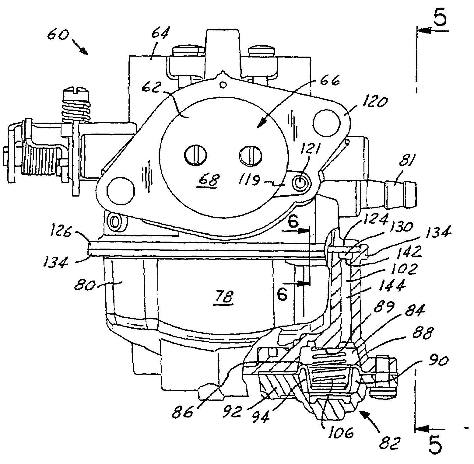
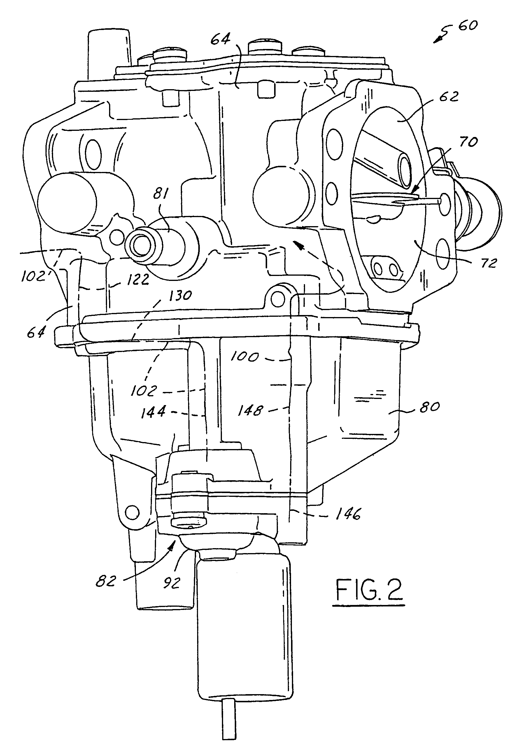
[0019]Referring in more detail to the drawings, FIGS. 2–8 illustrate a float-bowl type carburetor 60 embodying the present invention. The carburetor 60 has a fuel-and-air mixing passage 62 which extends through a carburetor body 64 for flowing a fuel-and-air mixture typically to the intake manifold of a four stroke engine or alternatively, to the crankcase of a two stroke combustion engine. A throttle valve 66 orientated in a downstream region 68 of the fuel-and-air mixing passage 62 generally controls the fuel-and-air mixture flow rate, which in-part controls the speed and power of the operating engine. Similarly, a choke valve 70 is orientated in an upstream region 72 of the mixing passage 62 and controls the amount of air flow through a venturi 74 of the mixing passage 62 which is located between the throttle and choke valves 66, 70.

[0020]Referring to FIGS. 2, 7 and 8, a main fuel feed tube or nozzle 76 communicates transversely with the mixing passage 62 at the venturi 74 to flo...


PUM

PropertyMeasurementUnit
angleaaaaaaaaaa
vacuumaaaaaaaaaa
speedaaaaaaaaaa

Abstract

A combustion engine carburetor with a fuel-and-air mixing passage extending through a body and a float bowl engaged sealably to the body. A vacuum actuated acceleration fuel pump is preferably carried by the float bowl and has a hose-less vacuum channel communicating between the fuel-and-air mixing passage downstream of a throttle valve and a vacuum chamber of the acceleration pump. A hose-less fuel discharge channel communicates between a supplemental fuel chamber of the acceleration pump and the fuel-and-air mixing passage between a venturi and a choke valve in the mixing passage. Preferably, the fuel discharge channel has an injecting bore portion defined by the body and being angled to direct fuel in a downstream direction toward the venturi to promote mixing with air.

Description

TECHNICAL FIELD[0001]This invention relates to combustion engine carburetors and more particularly to a carburetor having an acceleration fuel pump without external hoses.BACKGROUND OF THE INVENTION[0002]In a conventional prior art carburetor 20 as best illustrated in FIG. 1, a fuel-and-air mixing passage 22 extends through a carburetor body 24 providing a fuel-and-air mixture to the crankcase of a two cycle combustion engine or to an intake manifold of a four cycle engine. A throttle valve (not shown) orientated in a downstream region of the fuel-and-air mixing passage 22 controls the fuel-and-air mixture flow, which in-part controls the speed and power of the operating engine. Similarly, a choke valve 26 is orientated in an upstream region 28 of the mixing passage 22 and controls the amount of air flow through a venturi of the mixing passage 22 which is located between the throttle and choke valves. A main fuel feed tube communicates transversely with the mixing passage 22 at the ...

Claims


Application Information

Patent Timeline
Patent Type & Authority Patents(United States)
IPC IPC(8): F02M7/08
CPCF02M7/08
Inventor HACKER, DAVID D.
Owner WALBRO ENGINE MANAGEMENT
Why Eureka
Try Eureka