Shell press and method for forming a shell

Active Publication Date: 2007-12-04
STOLLE MACHINERY
View PDF21 Cites 29 Cited by
  • Summary
  • Abstract
  • Description
  • Claims
  • Application Information

AI Technical Summary

Benefits of technology

[0011]An object of the invention is to provide an apparatus and method for forming a shell that avoids excessive heat generation in the inner pressure sleev

Problems solved by technology

These approaches are not without certain limitations though.
The inner pressure sleeve mounted around a punch core, supported on a column of gas or supported on a piston can lead to the inner pressure sleeve heating up excessively in the shell forming process due to the loads that are applied to the inner pressure sleeve from formation of the chuck wall area of the shell being formed.
Excess heat generation in the inner pressure sleeve is not desirable in shell forming since the inner pressure sleeve can undergo thermal expansion and cause the press to form shells that do not meet the tolerances required by a can maker.
Also, the inner pressure sleeve mounted around a punch core, sup

Method used


Image

  • Shell press and method for forming a shell
  • Shell press and method for forming a shell
  • Shell press and method for forming a shell

Examples


Example

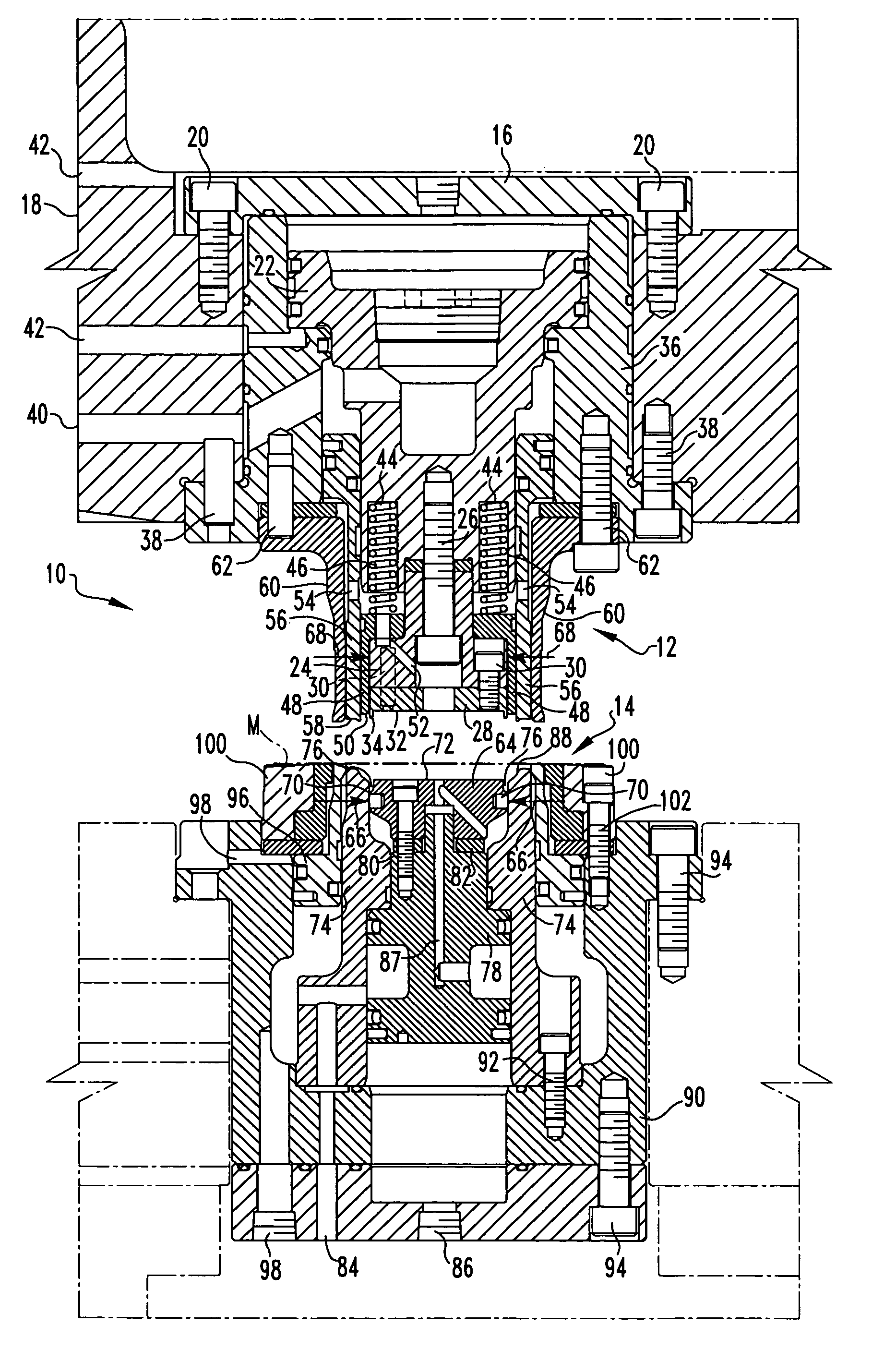
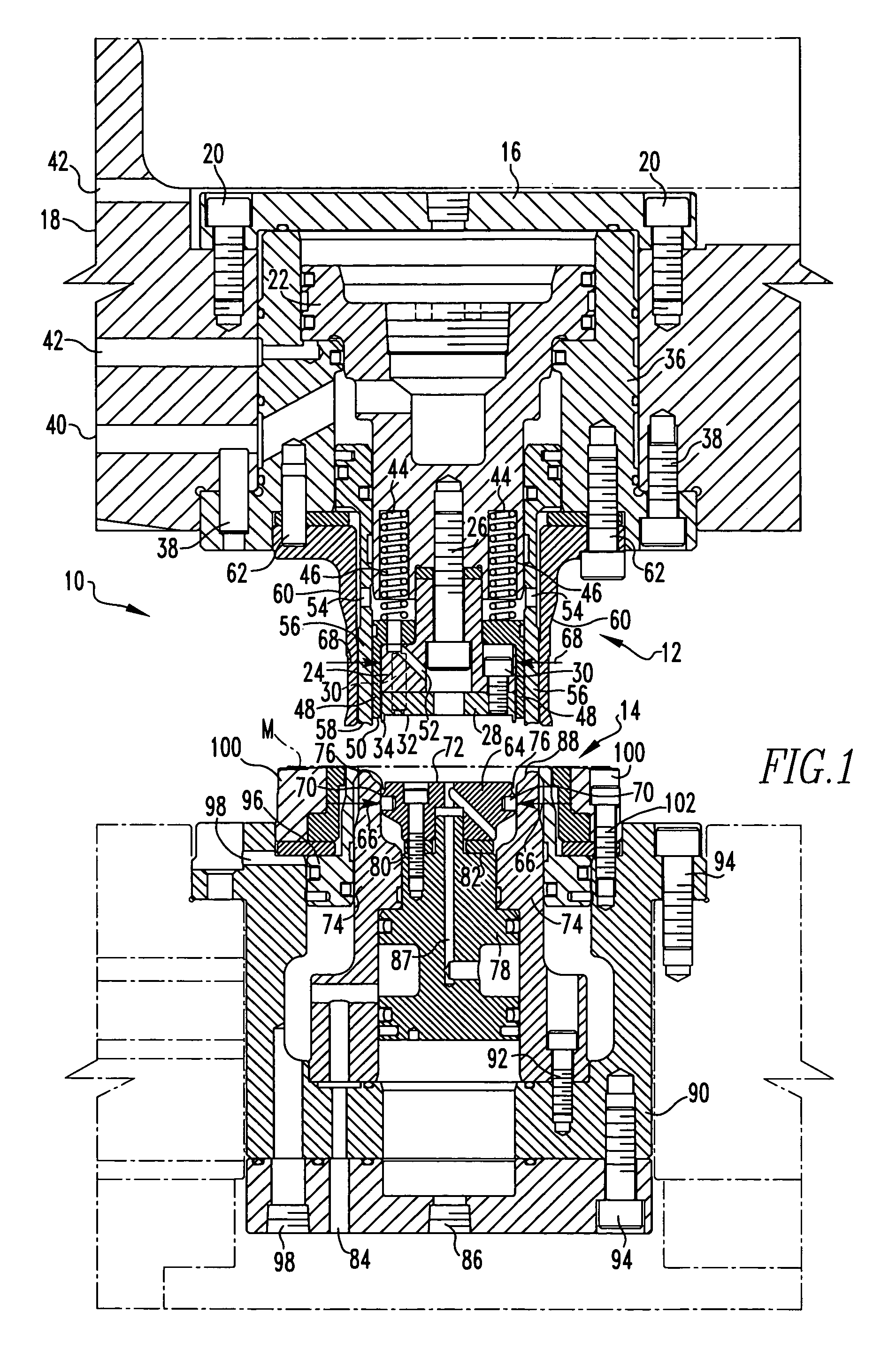
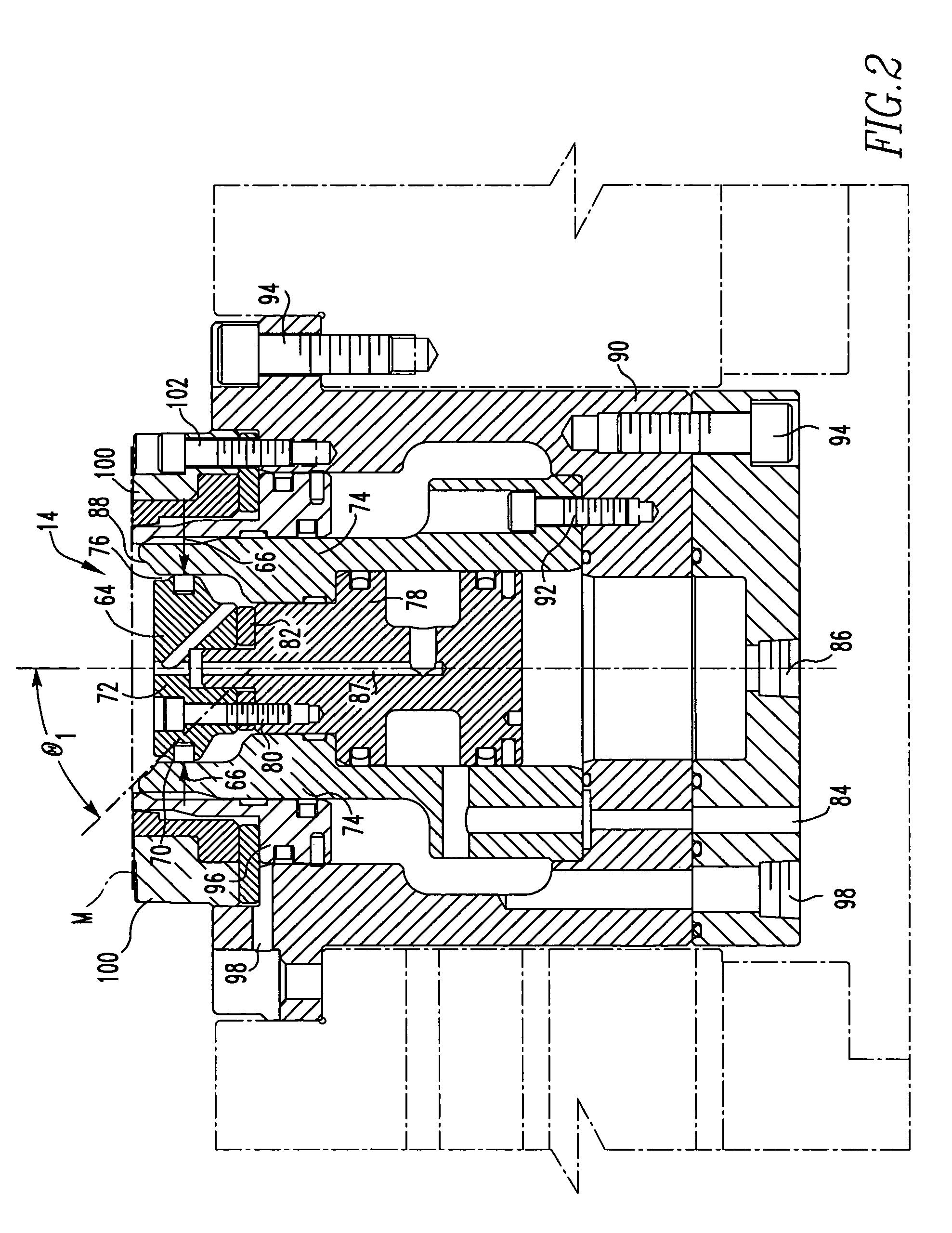
[0024]For purposes of the description hereinafter, the terms “upper”, “lower”, “vertical”, “horizontal”, “top”, “bottom”, “aft”, “behind”, and derivatives thereof shall relate to the invention, as it is oriented in the drawing FIGS. However, it is to be understood that the invention may assume various alternative configurations except where expressly specified to the contrary. It is also to be understood that the specific elements illustrated in the FIGS. and described in the following specification are simply exemplary embodiments of the invention. Therefore, specific dimensions, orientations and other physical characteristics related to the embodiments disclosed herein are not to be considered limiting.

[0025]As employed herein, the term “fastener” refers to any suitable fastening, connecting or tightening mechanism by way of example and not limitation, dowel pins, fasteners, rivets and the like. As employed herein, the statement that two or more parts are “coupled” together shall ...


PUM

PropertyMeasurementUnit
Angleaaaaaaaaaa
Pressureaaaaaaaaaa
Diameteraaaaaaaaaa

Abstract

An apparatus and method for forming a shell with a central panel and a chuck wall is provided. The apparatus and method employ the use of a biasing member to selectively bias and control movement of the inner pressure sleeve and a die core having an outer diameter equal to or greater than the outer diameter of the punch core. The apparatus and method can also be employed in a single action press or a double action press.

Description

FIELD OF THE INVENTION[0001]The invention generally relates to an apparatus and method for forming container end panels, commonly called shells, from a sheet of blanked material. More particularly, the invention relates to a press and method for forming the shell with the press having a biasing member that selectively biases and controls movement of the inner pressure sleeve and a die core having an outer diameter equal to or greater than the outer diameter of the punch core.BACKGROUND OF THE INVENTION[0002]The forming of can ends or shells for can bodies, namely aluminum or steel cans, is well-known in the art. Shells typically have a central panel connected to an inner panel wall which is connected to a countersink. The countersink is usually connected to a chuck wall of the shell which is connected to a peripheral curl that is structured to be seamed onto a can body.[0003]A representative patent disclosing shell forming is Bulso U.S. Pat. No. 4,716,755. As is typically seen, the ...

Claims


Application Information

Patent Timeline
IPC IPC(8): B21D22/10
CPCB21D51/38
Inventor TURNBULL, ROBERT DEANSTEFANSIC, DONNA REBECCA
Owner STOLLE MACHINERY
Why Eureka
Try Eureka