Eureka AIR delivers breakthrough ideas for toughest innovation challenges, trusted by R&D personnel around the world.

Ultralight cooking stove

Inactive Publication Date: 2007-04-19
KAY ROBERT L
View PDF5 Cites 0 Cited by
  • Summary
  • Abstract
  • Description
  • Claims
  • Application Information

AI Technical Summary

Benefits of technology

[0009] These objects are achieved in an ultralight stove comprising an unpressurized reservoir but self-pressurizing during stove operation by heat generated by burning of fuel in the reservoir which heat conducted back to the reservoir through a heat conduit central in the stove to heat fuel within the reservoir. With only a limited number of very small jet holes in the reservoir top through which vaporized fuel can escape, the reservoir becomes pressurized. Pressurized fuel vapor jets through the jet holes at a higher rate than from an unpressurized reservoir resulting in more heat generated for a faster heating of product on the stove.

Problems solved by technology

However, the heat they generate is limited by the rate of self-generated heat conducted back to the liquid fuel contained within the stove.
Because the conduction is limited to conduction through the container and radiation back to the stove from a pan on the stove, the rate of fuel consumption is not high and so the heat generated is consequently not high.
Thus, as vaporized fuel exits these holes and is burned, resulting flames directed toward the heat transfer plug heats it.

Method used


Image

  • Ultralight cooking stove
  • Ultralight cooking stove
  • Ultralight cooking stove

Examples


Embodiment Construction

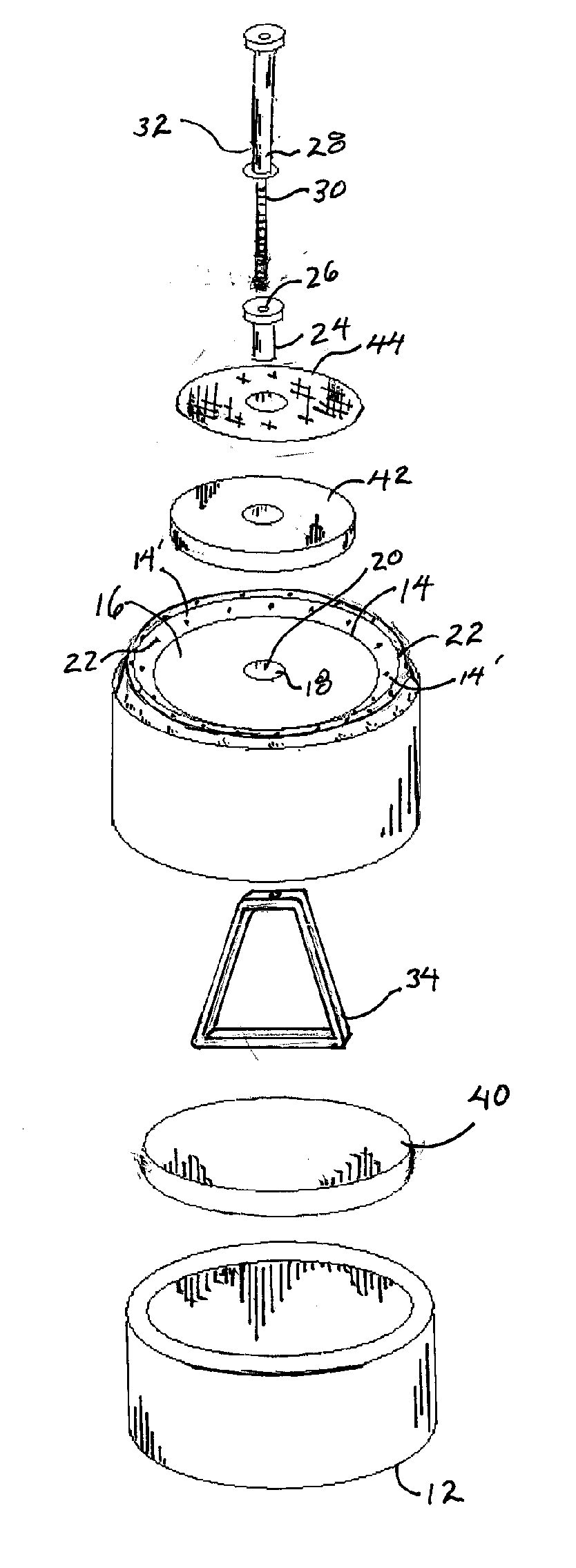
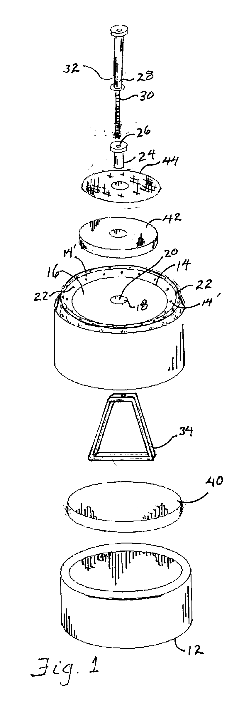
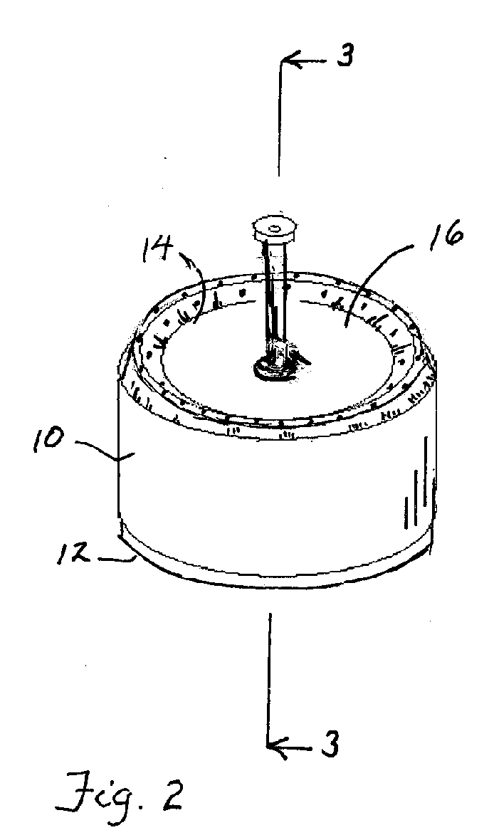
[0019] The ultralight stove of the present invention comprises a fuel reservoir 10 with a bottom 12 and a concave top 14 opening upward forming a recess 16 with a filler hole 18 at its center 20 such that fuel 100 poured into the recess 16 is funneled into the filler hole 18 through which fuel 100 may be loaded into the reservoir 10. A plurality of jet holes 22 in the reservoir top 14 opening into the reservoir 10 allows vaporized fuel to escape. Thus, the reservoir 10 remains unpressurized when the reservoir is unheated.

[0020] A rivet nut 24 with a threaded central hole 26 therethrough comprises the filler hole 18. A heat conducting heat transfer plug 28 that includes an externally threaded shaft 30 matches the threaded central hole 26 into which it is removably threaded, thus plugging the threaded central hole 26 during stove operation such that fuel escapes from the reservoir only through the jet holes 22. A heat transfer plug upward portion 32 extends upward from the stove top ...


PUM


Abstract

An ultralight stove comprises a fuel reservoir having a plurality of jet holes in the top through which vaporized fuel escapes and burns, a portion of which is directed toward a heat conducting heat transfer plug, heat from which being conducted through the heat transfer plug to the reservoir where it heats fuel in the reservoir causing increased fuel vaporization that pressurizes the reservoir which in turn causing pressurized fuel to escape through the jet holes resulting in increased heat to the heat transfer plug, the cycle continuing until a fuel consumption and temperature equilibrium is obtained where the heat transfer plug and reservoir reach maximum operating temperatures. A heat transfer conduit internal the reservoir extends centrally in the reservoir generally from the heat transfer plug to or to near the reservoir bottom therein conducting heat from the heat transfer plug to fuel in the reservoir. An external fuel absorber on the reservoir top receives fuel which when ignited initially heats the heat transfer plug to initiate stove operation such that before fuel in the external fuel absorber is spent, fuel in the reservoir is sufficiently heated to cause vaporized fuel to jet from said portion of the jet holes and be ignited. An internal fuel absorber internal the reservoir on the reservoir bottom in contact with the heat transfer module such that heat is transferred to the internal fuel absorber and any fuel in the internal fuel absorber.

Description

BACKGROUND [0001] 1. Field of the Invention [0002] This invention relates to backpack stoves and more specifically to ultra light stoves that are self-pressurizing during operation. [0003] 2. Prior Art [0004] It is known to have backpacking stoves, small and compact. These stoves are functional for the purpose for which they were designed, however, there remains a need for a simple but ultra light stove for the backpacking enthusiast seeking to minimize his or her backpack weight but requiring a stove that will generate intense heat. [0005] The most popular ultralight stoves are alcohol stoves. The fuel is readily available and they are simple to build from aluminum cans and other readily available parts. Alcohol stoves can be grouped into three types: Open Flame; Open Jet; and Closed Jet stoves. As connoted by its name, the open flame stove comprises exposed alcohol ignited for heat. Open Jet stoves can be made from a cut-down beverage can with a top half inserted into a bottom hal...

Claims


Application Information

Patent Timeline
IPC IPC(8): F24B3/00
CPCF24C3/14F24C5/20
Inventor KAY, ROBERTL
Owner KAY ROBERT L
Why Eureka
Eureka Blog
Learn More