
Shape memory alloy actuator

a technology of shape memory and actuator, applied in the direction of closed-cycle machines/engines, hot gas positive displacement engine plants, etc., can solve the problems of limited strain that can be applied to a sma, sma and largely martensite phase typically have a low yield strength, and are subjected to significant strain and plastic deformation, so as to improve the speed of actuation of sma actuators and increase the rate of heating

Inactive Publication Date: 2007-08-02
AUSTRALIEN NAT UNIV
View PDF7 Cites 46 Cited by
  • Summary
  • Abstract
  • Description
  • Claims
  • Application Information

AI Technical Summary

Benefits of technology

[0008] Preferred embodiments of the present invention seek to provide a controller for improving the speed of actuation of SMA actuators by increasing the rate at which they are heated.
[0017] When the wire is cool, having a substantially 100% martensite phase, the wire may be relatively easily strained or plastically deformed by the application of a relatively small force. The strained wire may then be heated by applying an electrical current through the wire to promote a phase change in the wire from martensite phase to austenite phase, such that the wire contracts and returns to its original shape. When the wire is heated sufficiently, the wire will have a substantially 100% austenite phase. To prevent damaging the SMA however, the temperature is maintained below a temperature associated with the SMA at which thermal damage will occur. To optimise the heating of the wire while maintaining the temperature below the temperature at which thermal damage will occur, embodiments of the present invention use the measured electrical resistance of the wire to determine a range for the temperature of the wire.
[0021] The net effect of an embodiment according to the present invention is a faster motion SMA actuator when compared with previous control schemes. By limiting the electrical current to the SMA element's safe limit current whenever the measured electrical resistance falls outside the safe resistance range for the element, a controller according to an embodiment of the present invention is able to use the measured electrical resistance of the SMA element to ensure that the element is not overheating or overheated. This allows a controller according to an embodiment of the present invention to apply a current greatly in excess of the SMA element's safe limit current, facilitating quicker heating, and therefore correspondingly a quicker phase change within the element and a quicker development of motive force. Applying a large current across a SMA element to heat the element quicker, even if the current is in excess of the safe limit current, is safe until the resistance of the element departs from the determined safe resistance range. Once the electrical resistance of the element departs from the safe resistance range however, the controller can no longer be sure that the SMA element is not overheating or overheated. At that point, the current must be reduced to a safe level or else the SMA may overheat.
[0022] Preferably, the controller progressively reduces the current applied through the SMA element as a function of the measured electrical resistance when heating the element instead of changing abruptly in response to the change in the electrical resistance. More preferably, the controller smoothly reduces the current applied through the SMA element as a function of the measured electrical resistance. The reduction of the current may occur over a range of electrical resistances within, but adjacent to the boundary of, safe resistance, for example. A progressive or smooth reduction in the applied current that avoids abrupt changes in the current, may be used in practice to improve the motion tracking accuracy of an embodiment of the present invention.
[0030] A preferred embodiment according to the present invention allows a SMA element to be held in a hot state (ie, largely austenite phase) should this become necessary with a further current significantly less than the safe limit current. The further current may be significantly less than the safe limit current quoted in or deducible from data sheets accompanying the SMA, while still being large enough to maintain the SMA in its hot phase. By choosing a lesser current below the data sheet value, it is possible to reduce the average power consumption of a SMA actuator during periods when rapid motion is not required.
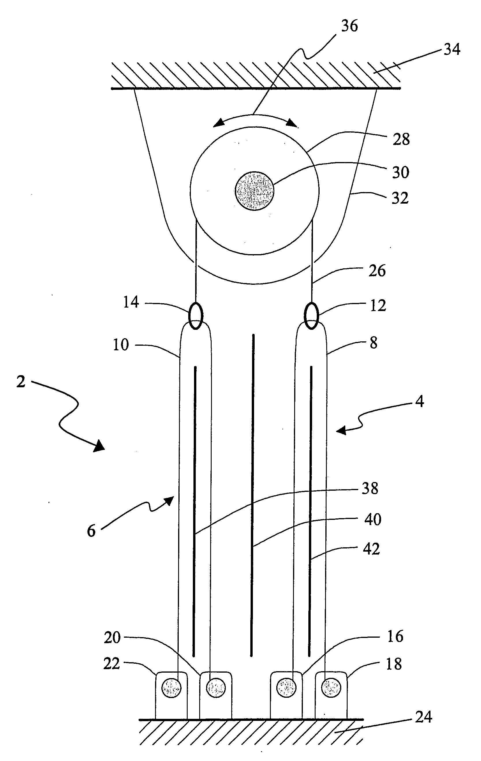
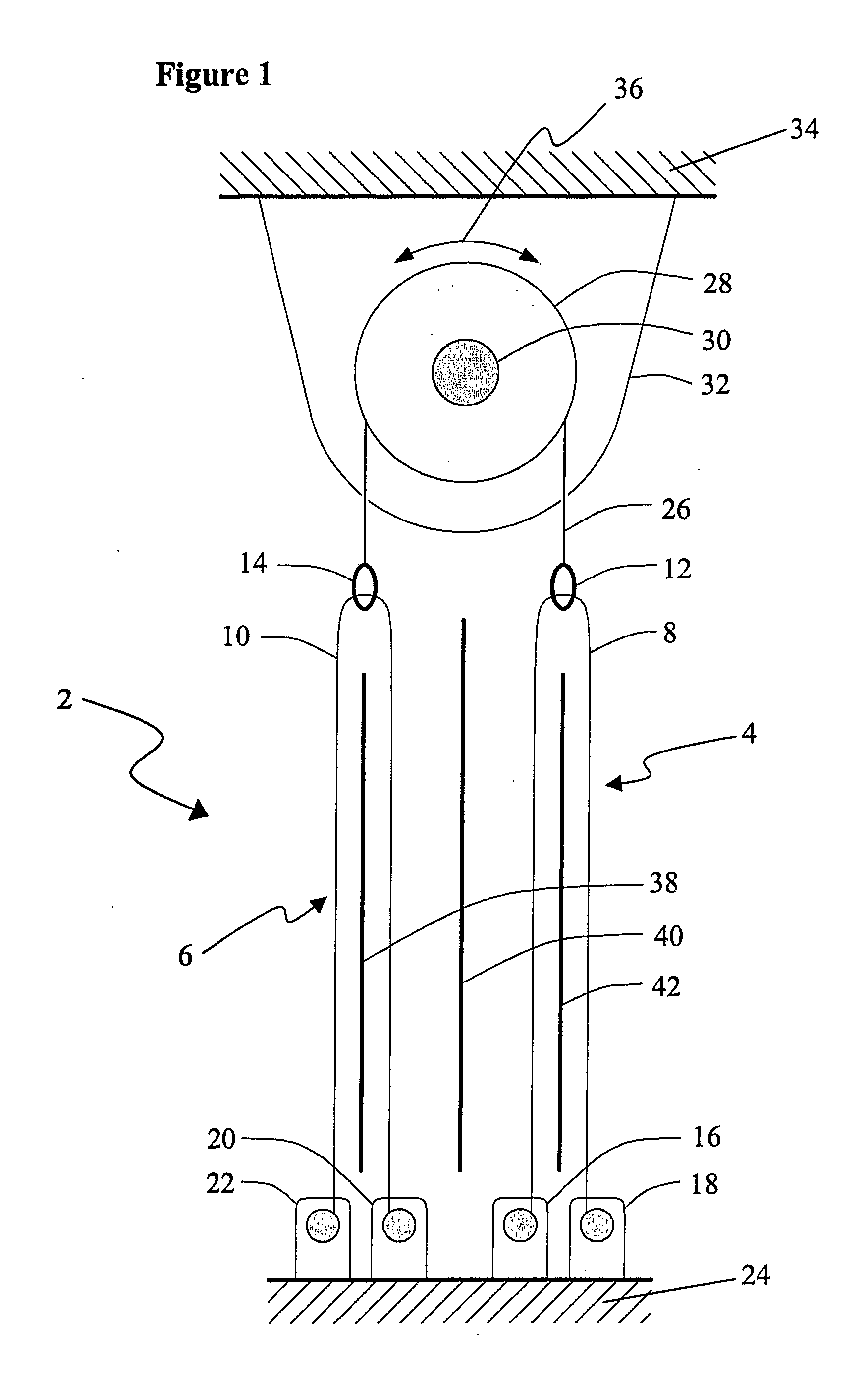
[0036] Preferably, the SMA actuator includes a second SMA element, the SMA elements being operably arranged so that the contraction of one of the SMA elements complementarily exerts a stretching force on the other of the SMA elements. In one practical form of the invention wherein the SMA elements are formed from a pair of SMA elements, when an initially stretched one of the pair of SMA elements having a largely martensite phase is contracted by heating, it may exert a stretching force on its cooler largely martensite phase antagonistic partner. Hence, as one of the elements contracts, the other of the elements is thereby strained and plastically deformed. This provides for the ongoing and substantially continuous operation of the actuator by the alternate heating of the elements without the need for a separate external mechanism for stretching the elements.

Problems solved by technology

A material formed from a SMA and having a largely martensite phase typically has a low yield strength, and can be subjected to significant strains and plastic deformation by the application of a relatively small force.
There is a limit to the strain that can be applied to a SMA in its martensite phase and fully recovered upon heating.
However, actuators employing nitinol elements generally don't use strains greater than about 4%, as strains higher than this can cause rapid fatigue.
SMAs having a largely austenite phase are normally incapable of tolerating strains of such a large magnitude.
Practical limitations of SMAs however, generally restrict the rate at which the wire or coil can be heated.
One approach for increasing the rate at which the wire or coil is heated may be to apply a larger current, but this approach is typically not employed in practice as it runs the risk of overheating the wire or coil and thereby permanently damaging the SMA.

Method used


Image

  • Shape memory alloy actuator
  • Shape memory alloy actuator
  • Shape memory alloy actuator

Examples


examples

[0081] The present invention is further described by the following non-limiting examples.

[0082]FIG. 3 is a graph of the electrical resistance of an approximately 1 meter long 0.1 mm diameter SMA wire such as the wire 8 shown in FIG. 1 (or similarly the wire 10, for example) formed from nitinol versus electrical heating input power during heating and cooling of the wire 8. A very slow power ramp was applied to the wire 8, starting at 0 watts, whereat the wire 8 has a substantially martensite phase. The power (or applied current) was increased at a rate of 0.1 watts per second to a power level of 4.8 watts which is just off the edge of the graph in FIG. 3, whereat the wire 8 has a substantially austenite phase. The power was then decreased at 0.1 watts per second to zero, whereat the wire 8 again has a substantially martensite phase. The slow rate at which the power was changed ensured that the wire 8 was always close to its equilibrium temperature for the power level being applied. ...


PUM


Abstract

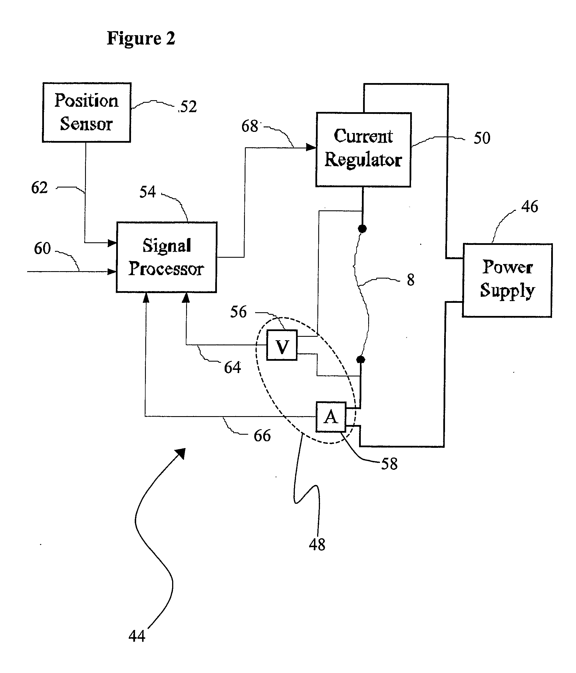
A controller (44) for a SMA actuator (2) includes an electgric power source (46) for applying an electric current through an SMA element (8), a sensor (48) to detect change in an electric resistance of the element (8); and a regulator (50) for controlling the magnitude of the applied electric current. The regulator (50) applies a first current above a safe limit current for the element (8) until a selected change in the electric resistance is detected and applies a second current less than the first current after the change is detected.

Description

FIELD OF THE INVENTION [0001] The present invention relates to a shape memory alloy actuator, and more particularly, to a controller for a shape memory alloy actuator. BACKGROUND OF THE INVENTION [0002] Shape memory alloys (hereinafter referred to as “SMA”s) are a specific group of electrically conducting materials sharing a particular physical property. In a solid state, they have two different crystalline states or phases, a low-temperature phase called martensite, and a high-temperature phase called austenite. [0003] A material formed from a SMA and having a largely martensite phase typically has a low yield strength, and can be subjected to significant strains and plastic deformation by the application of a relatively small force. If the deformed material is then heated so as to revert to a largely austenite phase, the material recovers its original shape. The shape recovery of SMAs is accompanied by a large force that is capable of doing a significant amount of mechanical work,...

Claims


Application Information

Patent Timeline
IPC IPC(8): F01B29/10F02G1/04F03G7/06
CPCF03G7/065
Inventor FEATHERSTONE, ROYTEH, YEE HARN
Owner AUSTRALIEN NAT UNIV
Learn More