Electric potential sensor, and image forming apparatus

a technology of electric potential and image forming apparatus, which is applied in the direction of resistance/reactance/impedence, optics, instruments, etc., can solve the problems of increasing the mass of a movable portion, the cost the limit to the reduction of the size of the conventional mems electrostatic sensor, etc., to achieve lightening of the mass of the movable portion, reducing the size of the conventional mems electrostati

Inactive Publication Date: 2005-11-15
CANON KK
View PDF5 Cites 34 Cited by
  • Summary
  • Abstract
  • Description
  • Claims
  • Application Information

AI Technical Summary

Benefits of technology

[0018]It is possible to adopt a construction in which at least two electrically-conductive movable shutters and at least two current injecting units are provided, and the electrically-conductive movable shutters are movable owing to interaction between the currents which are injected into the electrically-conductive movable shutters by the current injecting units, respectively, in a direction approximately perpendicular to a moving direction of the electrically-conductive movable shutter. Also in such a construction, the electrically-conductive movable shutters constitute a portion of the actuator, so that there is no need to provide an actuator unit in a totally separate form, leading to a decrease in its size. Further, the individual electrically-conductive movable shutters can be independently moved, so that mass of the movable portion can be lightened. Accordingly, its moving speed can be increased, and the sensitivity of the sensor can be hence enhanced. Moreover, no high voltage is needed to drive the electrically-conductive movable shutters, and accordingly the cost of the driving unit can be reduced.
[0019]When the electrically-conductive movable shutter is shaped into an electrically-conductive movable shutter which is elastically supported movably, the movable shutter can be moved without its motion being disturbed by friction. Further, when the structure is constructed such that the driving frequency of the electrically-conductive movable shutter can be approximately equalized with its mechanical resonance frequency, consumption of electrical power for achieving a given amplitude of the motion can be largely reduced.
[0020]Further, it is possible to construct a structure in which there are arranged first and second detecting electrodes which are to be placed facing the measurement object, and a differential processing unit for differentially processing outputs supplied from the first and second detecting electrodes, the electrically-conductive movable shutter can selectively take a first state or a second state, the first detecting electrode is exposed to the measurement object more (typically, exposed approximately entirely) at the time when the electrically-conductive movable shutter takes the first state than at the time when the electrically-conductive movable shutter takes the second state, and the second detecting electrode is exposed to the measurement object less (typically, shielded approximately entirely) at the time when the electrically-conductive movable shutter takes the first state than at the time when the electrically-conductive movable shutter takes the second state. In such a construction, the first and second detecting electrodes can be disposed close to each other, so that the effective area of the detecting electrode can be increased. Further, since the outputs from the first and second detecting electrodes are differentially processed to obtain a signal, the sensitivity can be increased even if the size is relatively small.

Problems solved by technology

Therefore, there is a limitation to reduction of the size of the conventional MEMS electrostatic sensor, and its cost increases.
Further, since the driver component 1010 and the sensor component 1020 move together, mass of a movable portion is likely to increase, and it is hence difficult to increase the driving frequency.
The detecting sensitivity dC / dt of the electrostatic sensor is also proportional to the driving frequency, and accordingly the detecting sensitivity is difficult to increase.

Method used


Image

  • Electric potential sensor, and image forming apparatus
  • Electric potential sensor, and image forming apparatus
  • Electric potential sensor, and image forming apparatus

Examples


first embodiment

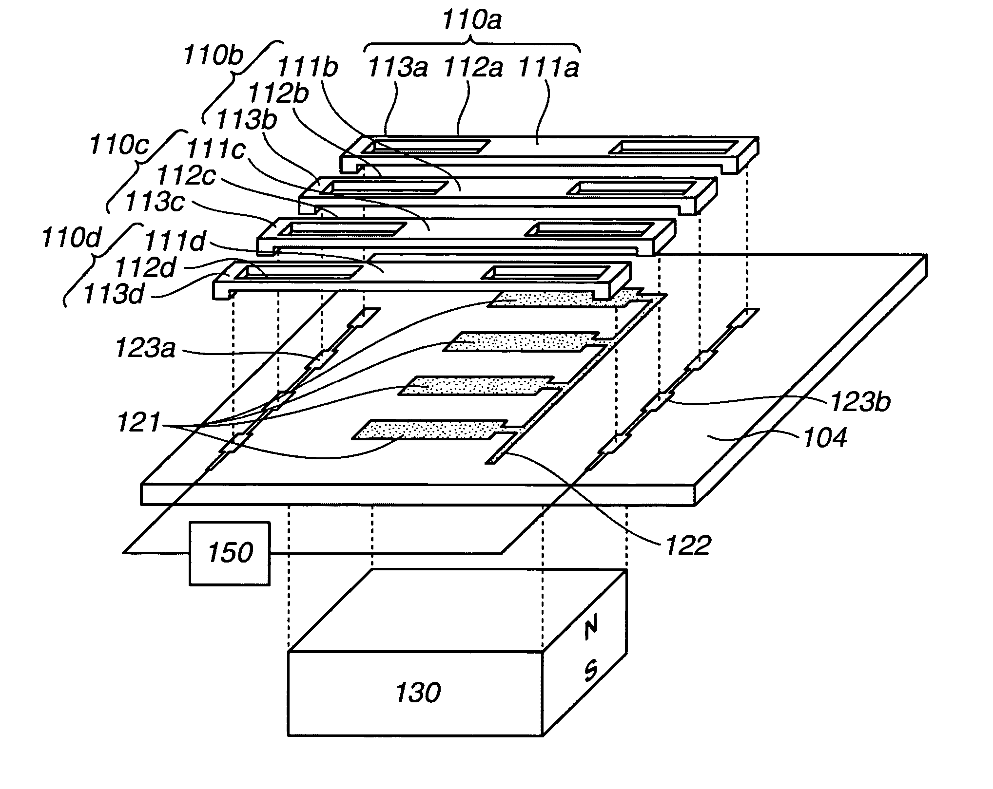
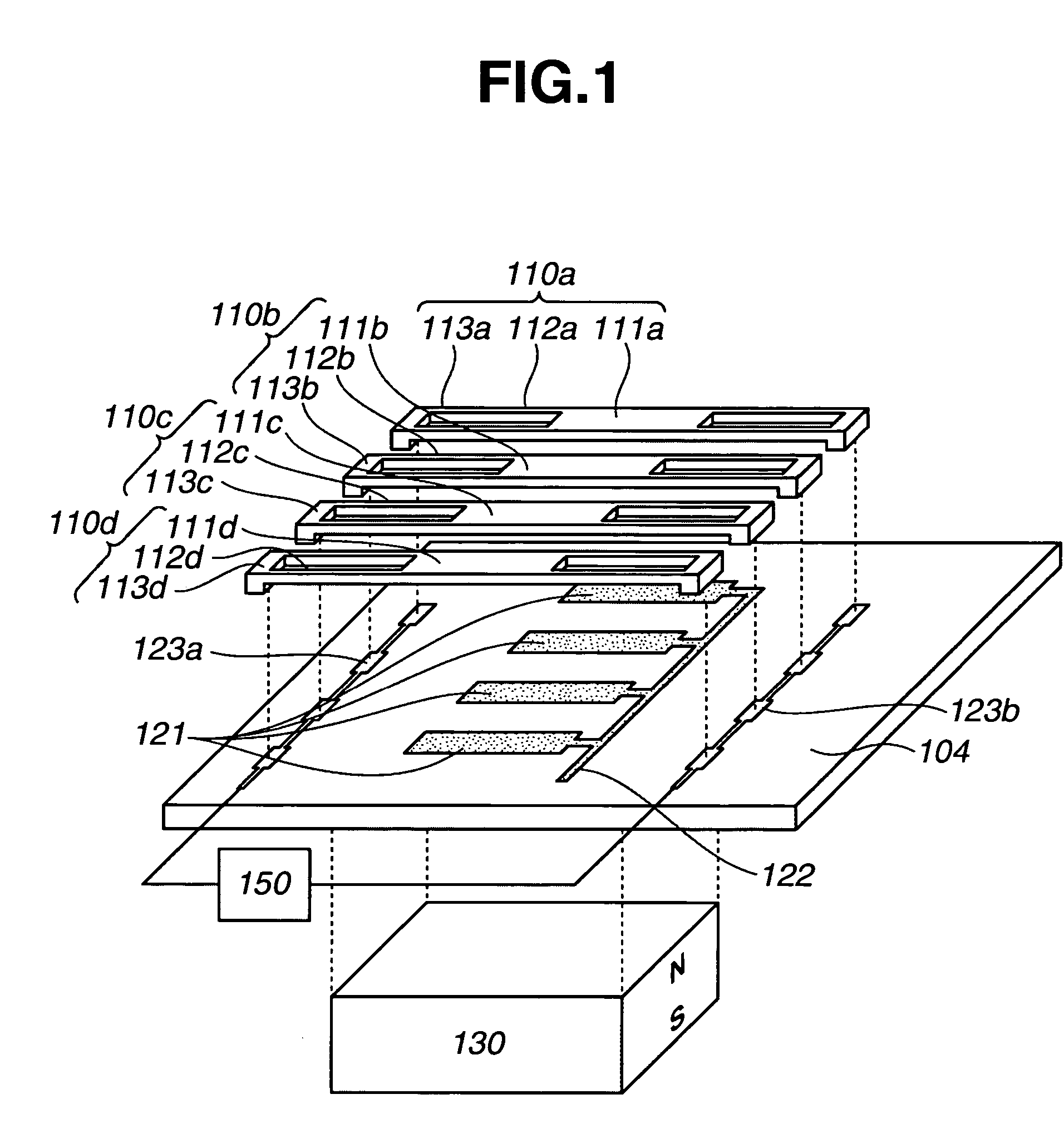
[0038]FIG. 1 illustrates a disassembled structure of a first embodiment directed to an electric potential sensor. As illustrated in FIG. 1, a detecting electrode assembly 121, a takeout electrode 122 for the detecting electrode assembly 121, and takeout electrodes 123a and 123b for driving are patterned on a substrate 104. The detecting electrode assembly 121 consists of a set of detecting electrodes which are spaced from each other and electrically connected to each other.

[0039]Movable shutter units 110a to 110d are comprised of shielding members 110a to 110d, parallel hinge suspensions 112a to 112d, and fixing members 113a to 113d, respectively. Those portions 111a to 111d, 112a to 112d, and 113a to 113d are formed in a united form with electrically-conductive material, respectively. Each of the fixing members 113a to 113d is fixedly bonded to the driving takeout electrodes 123a and 123b. The shielding members 111a to 111d are supported by the parallel hinge suspensions 112a to 11...

second embodiment

[0046]FIG. 3 illustrates a disassembled structure of a second embodiment directed to an electric potential sensor. As illustrated in FIG. 3, two detecting electrode assemblies 221a and 221b, takeout electrodes 222a and 222b for the detecting electrode assemblies 221a and 221b, and takeout electrodes 223a and 223b for driving are patterned on a substrate 204. Each of the detecting electrode assemblies 221a and 221b consists of a set of detecting electrodes which are spaced from each other and electrically connected to each other by each of the takeout electrodes 222a and 222b for the detecting electrode assemblies 221a and 221b. Detecting electrodes of the detecting electrode assemblies 221a and 221b are spaced from each other such that they cannot be electrically shorted therebetween.

[0047]Movable shutter units 210a to 210d are comprised of shielding members 211a to 211d, parallel hinge suspensions 212a to 212d, and fixing members 213a to 213d, respectively. Those portions 211a to 2...

third embodiment

[0054]FIG. 5 illustrates a disassembled structure of a third embodiment directed to an electric potential sensor. As illustrated in FIG. 5, two detecting electrode assemblies 321a and 321b, takeout electrodes 322a and 322b for the detecting electrode assemblies 321a and 321b, coupling electrodes 323a to 323c, and takeout electrodes 324a and 324b for driving are patterned on a substrate 304. Each of the detecting electrode assemblies 321a and 321b consists of a set of detecting electrodes (only one detecting electrode of the detecting electrode assembly 321b is shown in FIG. 5) which are spaced from each other and electrically connected to each other by each of the takeout electrodes 322a and 322b for the detecting electrode assemblies 321a and 321b. Detecting electrodes of the detecting electrode assemblies 321a and 321b are spaced from each other such that they cannot be electrically shorted therebetween.

[0055]Movable shutter units 310a to 310d are comprised of shielding members 31...


PUM


Abstract

Disclosed in a non-contacting electric potential sensor capable of being readily reduced in its size, which includes a detecting electrode, an electrically-conductive movable shutter, and a driving unit for driving the electrically-conductive movable shutter. The detecting electrode is to be placed facing a measurement object whose electric potential is to be measured. The electrically-conductive movable shutter is disposed so as to be movably located in a spacing formed between the detecting electrode and the measurement object when the detecting electrode is placed facing the measurement object, so that an exposure degree of the detecting electrode against the measurement object can be controlled. The driving unit includes a current injecting unit for selectively injecting current into the electrically-conductive movable shutter in a direction approximately perpendicular to a moving direction of the electrically-conductive movable shutter.

Description

BACKGROUND OF THE INVENTION[0001]1. Field of the Invention[0002]The present invention relates to a non-contacting electric potential sensor capable of being fabricated using micro-electro-mechanical-systems (MEMS) technology, and an image forming apparatus using the electric potential sensor.[0003]2. Description of the Related Background Art[0004]As a sensor for measuring a surface electric potential of an object to be measured (a measurement object), a variable capacitive coupling electric potential sensor of a mechanical type is known. FIG. 9 shows a principle of the mechanical type variable capacitive coupling potential sensor. A measurement object 1099 has an electric potential V relative to a ground potential. A detecting electrode 1021 is disposed facing the measurement object, and a movable shutter 1025 is arranged right above the detecting electrode 1021. Upon motion of the movable shutter 1025, an electrostatic capacitance C between the measurement object 1099 and the detec...

Claims


Application Information

Patent Timeline
Patent Type & Authority Patents(United States)
IPC IPC(8): G01D5/12G01D5/241G01R29/12G03G21/00
CPCG01D5/2412G01R29/12G01D5/2403
Inventor YASUDA, SUSUMUUSHIJIMA, TAKASHIZAITSU, YOSHITAKAICHIMURA, YOSHIKATSU
Owner CANON KK
Why Eureka
Try Eureka