Micro mirror device with adjacently suspended spring and method for the same

a technology of micro mirror and adjacent suspension spring, which is applied in the field of microelectromechanical systems for display systems, can solve the problems of increasing the switching frequency or the speed by which the mirror can pivot, the design dilemma of the hinge stiffness, and the inability to adjust the actuation speed of the mirror, so as to achieve the effect of increasing the actuation speed

Active Publication Date: 2005-09-08
SAMSUNG ELECTRONICS CO LTD
View PDF11 Cites 30 Cited by
  • Summary
  • Abstract
  • Description
  • Claims
  • Application Information

AI Technical Summary

Benefits of technology

[0006] The present invention relates to a method and apparatus providing a micro-mirror device configured to increase actuation speed thereof. The micro-mirror device includes a substrate, a mirror, a spring member and at least one adjacent micro-mirror device. The mirror is suspended over the substrate and configured to deflect in response to an actuation force. The spring member is suspended between the substrate and the mirror. Further, the spring member is configured to store energy upon being deflected by the mirror and is configured to release the stored energy to force the mirror to another position. The at least one adjacent micro-mirror device is positioned over the substrate adjacent the mirror and is configured to suspend the spring member.

Problems solved by technology

However, there is often a design dilemma with respect to the stiffness of the hinge.
However, the stiff hinge requires a greater voltage for deflecting the mirror.
In addition, this type of micro-mirror device, immersed in a gas, often has problems in the switching frequency or speed by which the mirror can pivot.
In particular, the mirror often has a tendency to stick to the landing sites due to a variety of forces such as the van der Waals force generated by water vapor present on the device surface and intermetallic bonding.
Although this type of micro-mirror device does not experience the same problems of sticking, the pivoting mirror experiences a fluidic dampening effect within the dielectric liquid.
Such a dampening effect may result in loss of speed and frequency of the pivoting mirror, which causes limitations in the type of applications with which the micro-mirror devices can be implemented, and / or causes a corresponding time-delay by which images are clearly viewed in, for example, a display system.

Method used


Image

  • Micro mirror device with adjacently suspended spring and method for the same
  • Micro mirror device with adjacently suspended spring and method for the same
  • Micro mirror device with adjacently suspended spring and method for the same

Examples


Embodiment Construction

[0014] Reference will now be made to the exemplary embodiments illustrated in the drawings, and specific language will be used herein to describe the same. It will nevertheless be understood that no limitation of the scope of the invention is thereby intended. Alterations and further modifications of the inventive features illustrated herein, and additional applications of the principles of the inventions as illustrated herein, which would occur to one skilled in the relevant art and having possession of this disclosure, are to be considered within the scope of the invention.

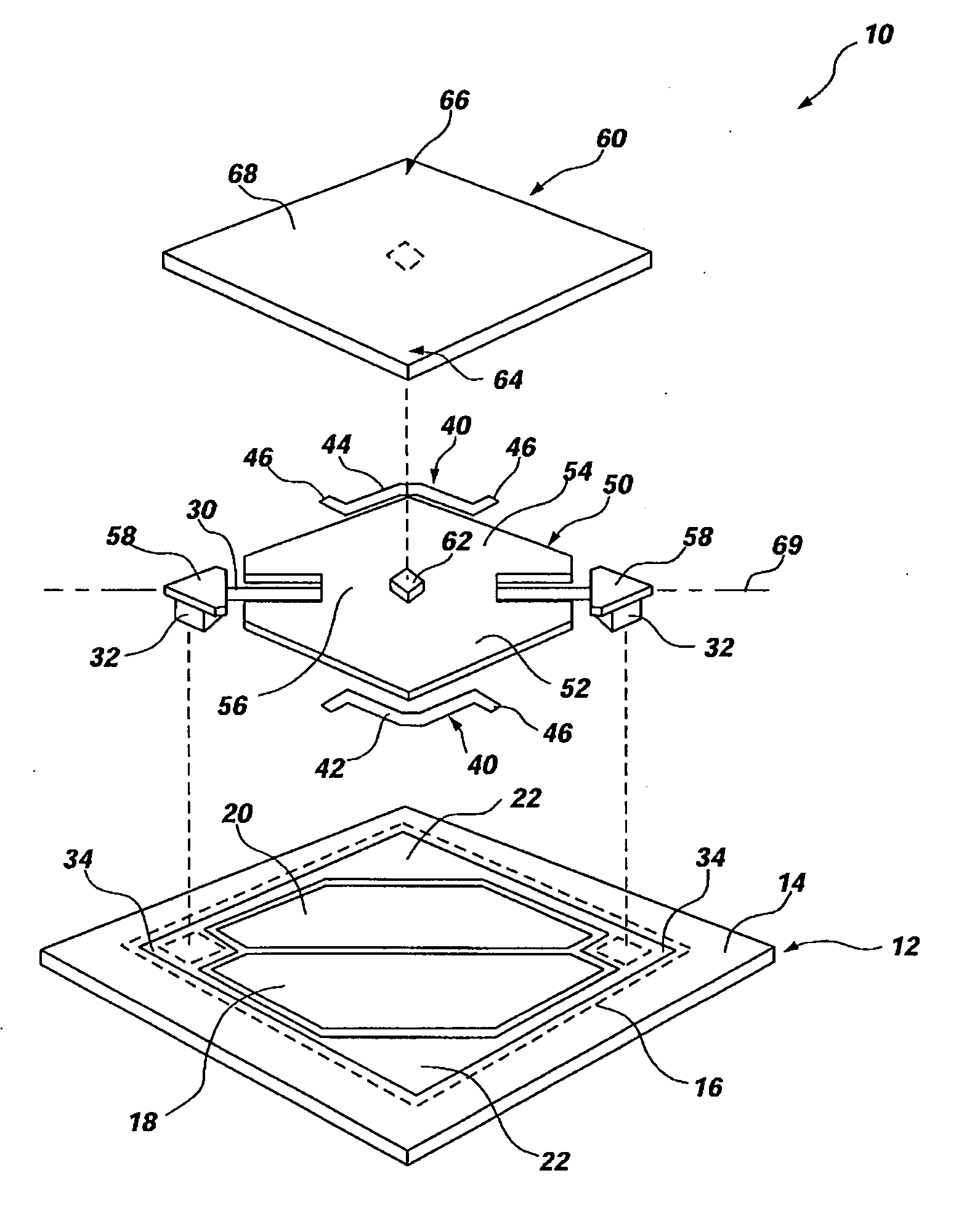
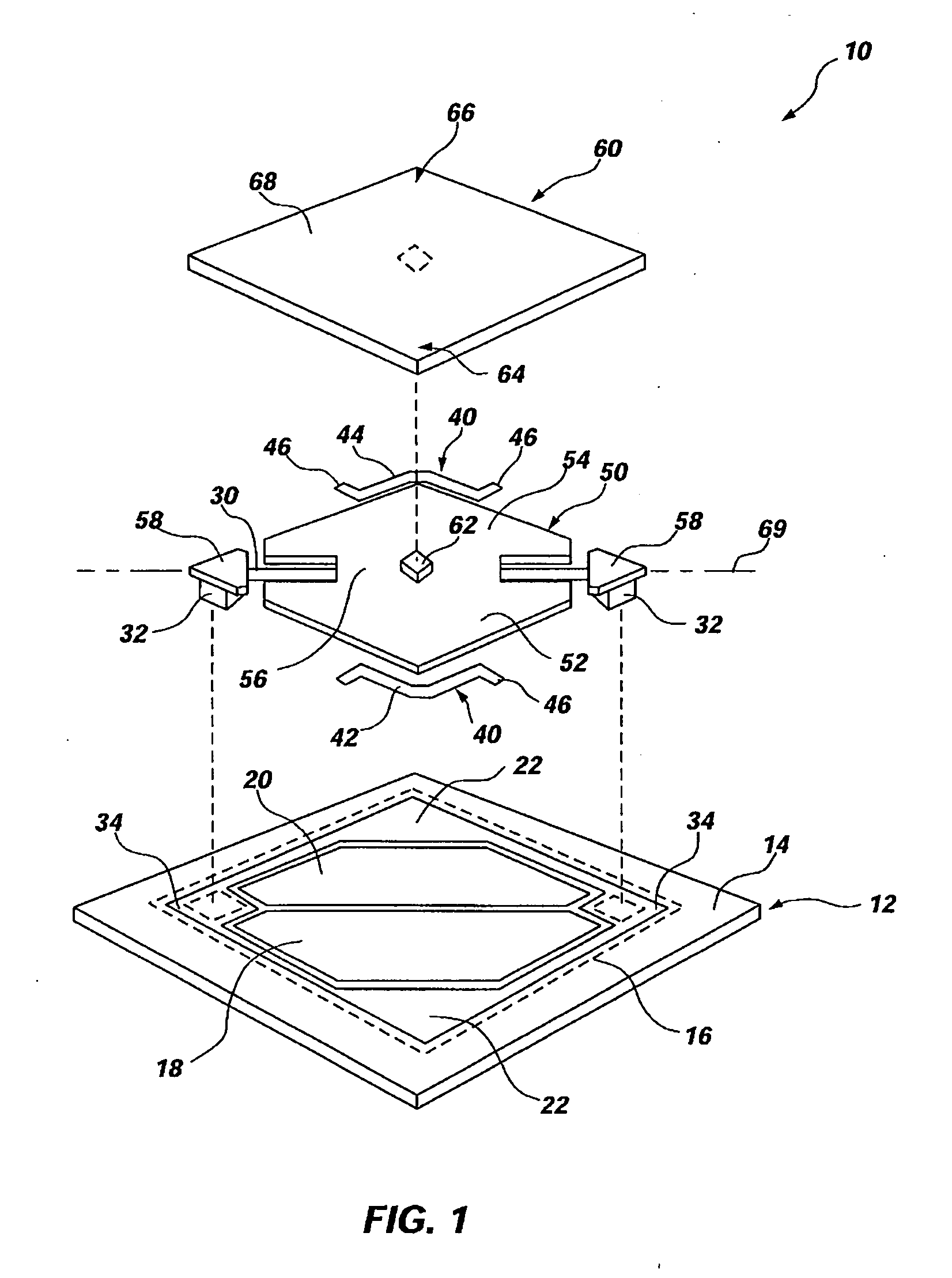
[0015]FIG. 1 illustrates, in exploded form, an embodiment of a micro-mirror device 10 configured to increase the actuation speed thereof. The micro-mirror device 10 can include and be formed over a substrate 12 with address electrodes 18, 20 formed thereon. The micro-mirror device 10 can include a hinge member 30, a spring member 40, a yoke 50 and a mirror 60 each suspended above the substrate 12 and each of wh...


PUM


Abstract

A method and apparatus providing a micro-mirror device configured to increase actuation speed thereof. The micro-mirror device includes a substrate, a mirror, a spring member and at least one adjacent micro-mirror device. The mirror is suspended over the substrate and configured to deflect in response to an actuation force. The spring member is suspended between the substrate and the mirror. Further, the spring member is configured to store energy upon being deflected by the mirror and is configured to release the stored energy to force the mirror to another position. The at least one adjacent micro-mirror device is positioned over the substrate adjacent the mirror and is configured to suspend the spring member.

Description

FIELD OF THE INVENTION [0001] The present invention relates generally to micro-electromechanical systems for a display system. More particularly, the present invention relates to increasing actuation speed of a micro-mirror device. BACKGROUND OF THE INVENTION [0002] Micro-mirror devices are well known and often referred to as micro-electromechanical systems (MEMS). Such micro-mirror devices have been formed on insulators or other substrates using commonly known micro-electronic fabrication techniques, such as photolithography, vapor deposition, and etching. The micro-mirror device can be operated as a light modulator for amplitude and / or phase modulation of incident light. One application of a micro-mirror device is within a display system. As such, multiple micro-mirror devices are arranged in an array such that each micro-mirror device constitutes one cell or pixel of the display system. [0003] One conventional micro-mirror device includes an electrostatically actuated mirror imme...

Claims


Application Information

Patent Timeline
Patent Type & Authority Applications(United States)
IPC IPC(8): G02B26/00
CPCB81B3/0045B81B2201/042B81B2203/0109Y10S359/904G02B1/06G02B26/0841B81B2203/058
Inventor FAASE, KENNETHJILANI, ADELGUO, JAMESCRUZ-URIBE, TORRY S.
Owner SAMSUNG ELECTRONICS CO LTD
Why Eureka
Try Eureka