Lens driving apparatus

Active Publication Date: 2005-08-18
NEW SHICOH MOTOR CO LTD
View PDF3 Cites 34 Cited by
  • Summary
  • Abstract
  • Description
  • Claims
  • Application Information

AI Technical Summary

Benefits of technology

[0039] According to the sixth aspect of the present invention, similar to the first to fifth aspects of the present invention, since the lens is linearly moved in the direction of the optical axis by the electromagnetic force caused by passing current through the coil, the direction of thrust matches the moving direction of the lens. Accordingly, the amount of drive loss may be extremely small. This makes it possible to accelerate the moving speed of the lens and improve responsivity. Namely, since the amount of drive loss is small and responsivity and mobility are excellent, the lens can be efficiently moved in the direction of the optical axis by a desired amount in the narrow space and this is excellent in mounting on the small size camera. The lens support members can be smoothly and stably moved by the guide rails and the slide member.
[0040] Since the magnet or yoke, which generates an electromagnetic force, is fixed to the lens driving members driven on receiving the electromagnetic force, the miniaturization of the entire linear driving apparatus can be improved.
[0041] The magnet preferably includes a plurality of magnets arranged in series along a direction where a driving member is moved, and

Problems solved by technology

Accordingly, unlike the conventional art, there is no need of us

Method used


Image

  • Lens driving apparatus
  • Lens driving apparatus
  • Lens driving apparatus

Examples


first embodiment

[0073] (First Embodiment)

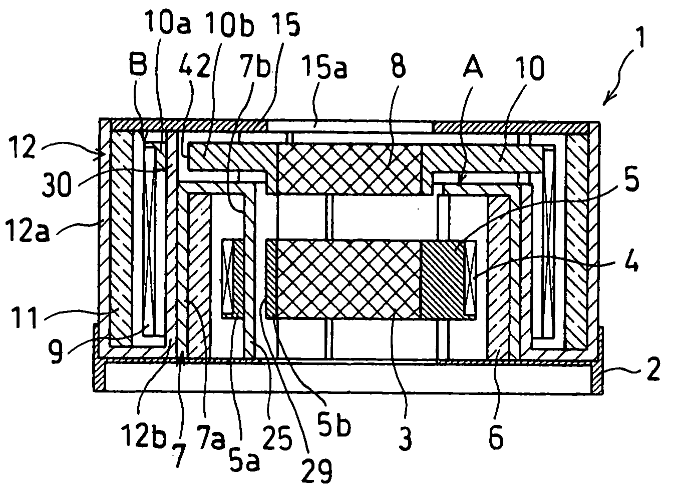
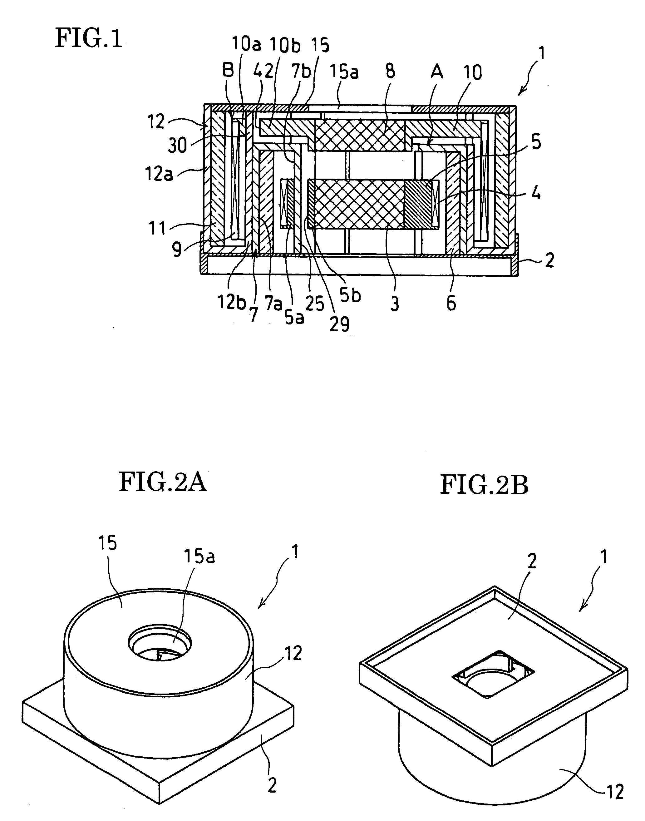
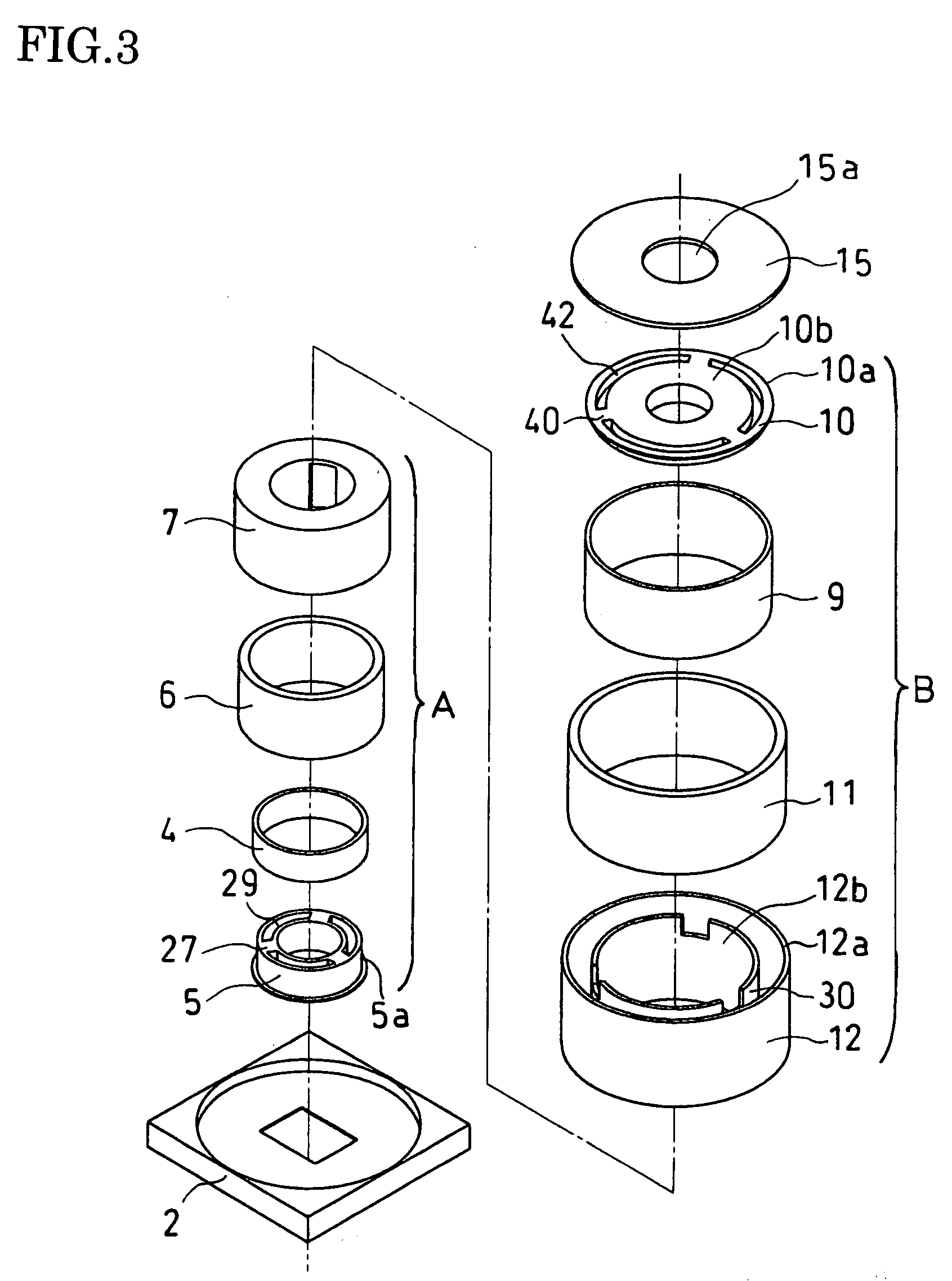
[0074] FIGS.1 to 3 show a first embodiment of the present invention.

[0075] A lens driving apparatus 1 according to the first embodiment is a lens driving apparatus for an autofocus camera incorporated into a cellular phone, and has a first lens driving section A and a second lens driving section B. The first lens driving section A has a first yoke 7 with a rectangular U-shape cross section and a cylindrical shape. The first yoke 7 is attached to a base 2.

[0076] The first yoke 7 has an inner peripheral wall 7b and an outer peripheral wall 7a, which are arranged to be substantially concentric with other. The inner peripheral wall 7b has multiple slidably contacting portions 25 formed along the peripheral direction with a predetermined distance. In the interior of the rectangular U-shape of the first yoke 7, a magnet 6 is provided. Moreover, a coil 4 is provided at an inner peripheral side of the magnet 6 in the interior of the rectangular U-shape. In this ca...

second embodiment

[0094] (Second Embodiment)

[0095]FIGS. 5 and 6 illustrate a second embodiment of the present invention. In the second embodiment, the second lens driving section B shares the yoke 7 and the magnet 6 with the first lens driving section A, and has the first coil 4 positioned at an inner peripheral side of the second coil 9 of the second lens driving section B. The second coil 9 is formed as a long pipe that encloses the first coil 4 externally. The first coil 4 is formed as a short pipe that completely fits in the interior of the second coil 9.

[0096] Moreover, the first coil 4 is fixed to an outer periphery of the first lens support member 5 positioned at the inner peripheral side of the second coil 9. The first lens support member 5 is substantially cylindrically shaped and contains the lens 3 in its interior, and is attached to be slidable on the inner peripheral side of the yoke 7 along the optical axis.

[0097] The second embodiment can obtain the same effect as that of the first e...

third embodiment

[0101] (Third Embodiment)

[0102]FIGS. 8 and 9 illustrate a third embodiment of the present invention. In the third embodiment, unlike the aforementioned embodiment, no second yoke 12 is provided and only yoke 7 is provided. The second lens support member 10 is placed at the inner peripheral side of the yoke 7. The second coil 9 is fixed to the outer periphery of the second lens support member 10. The second lens support member 10 is substantially cylindrically shaped and contains the lens 8 in its interior, and is attached to be slidable on the inner peripheral side of the yoke 7 along the optical axis.

[0103] In the third embodiment, the distance between the magnet 6 and the second coil 9 is set to be substantially equal to the distance between the magnet 6 and the first coil 4.

[0104] The third embodiment also has the same effect as that of the first embodiment. More specifically, since the first and second lens support members 5 and 10 are linearly moved in the direction of the op...


PUM


Abstract

A lens driving apparatus includes a first yoke 7 having an inner peripheral wall 7a and an outer peripheral wall 7b placed to be concentric with each other and forming a rectangular U-shape cross section and a cylindrical shape; a second yoke 12 placed at an outer side of the first yoke 7 be concentric with the first yoke 7 and forming a rectangular U-shape cross section and a cylindrical shape; a base 2; a first magnet 6 and a first coil 4 arranged in a rectangular U-shape interior of the first yoke 7; a second magnet 11 and a second coil 9 arranged in a rectangular U-shape interior of the second yoke 12; a first lens support member 5; and a second lens support member 10. The second lens support member 10 is placed at an inner peripheral side of the second yoke 12 and having the second coil 9 fixed onto an outer periphery. The first lens support member 5 is linearly moved in a direction of an optical axis of a lens by an electromagnetic force caused by passing current through the first coil 4. The second lens support member is linearly moved in a direction of an optical axis of a lens by an electromagnetic force caused by passing current through the second coil 9.

Description

BACKGROUND OF THE INVENTION [0001] 1. Field of the Invention [0002] The present invention relates to a lens driving apparatus that drives a zoom lens and an autofocus lens, which are used in a small-sized portable camera built in a digital camera, a cellular phone and the like. [0003] 2. Description of the Related Art [0004] Conventionally, such a lens driving apparatus that performs both autofocusing and scaling with a zoom lens and a focus lens is known as disclosed in, for example, Unexamined Japanese Patent Publication Hei 7-140523. The lens driving apparatus in this conventional art converts a rotational movement using a ball screw and the like to a linear movement to move the lens in a direction of an optical axis. [0005] By the way, in the lens driving apparatus, which are used in a small-sized portable camera, it is required that the lens be efficiently moved in a direction of an optical axis by a desired amount in a narrow space. [0006] However, when the structure in which ...

Claims


Application Information

Patent Timeline
IPC IPC(8): G03B3/10G02B7/08G02B7/09G02B7/10G02B7/28G11B7/00
CPCG02B7/08G02B7/282G02B7/102G03B3/10G02B7/09
Inventor SHIRAKI, MANABUASAKAWA, SATOSHISEKIGUCHI, NAOKIYOSHIE, MORIMASA
Owner NEW SHICOH MOTOR CO LTD
Why Eureka
Try Eureka