Electric oven applying an induction heating at both sides of the cavity

Inactive Publication Date: 2005-03-08
LG ELECTRONICS INC
View PDF6 Cites 43 Cited by
  • Summary
  • Abstract
  • Description
  • Claims
  • Application Information

AI Technical Summary

Benefits of technology

Therefore, an object of the present invention is to provide an electric oven which can transmit he

Problems solved by technology

However, the sheath heater takes much time in increasing temperature up to a saturation temperature since s

Method used


Image

  • Electric oven applying an induction heating at both sides of the cavity
  • Electric oven applying an induction heating at both sides of the cavity
  • Electric oven applying an induction heating at both sides of the cavity

Examples


Example

Reference will now be made in detail to the preferred embodiments of the present invention, examples of which are illustrated in the accompanying drawings.

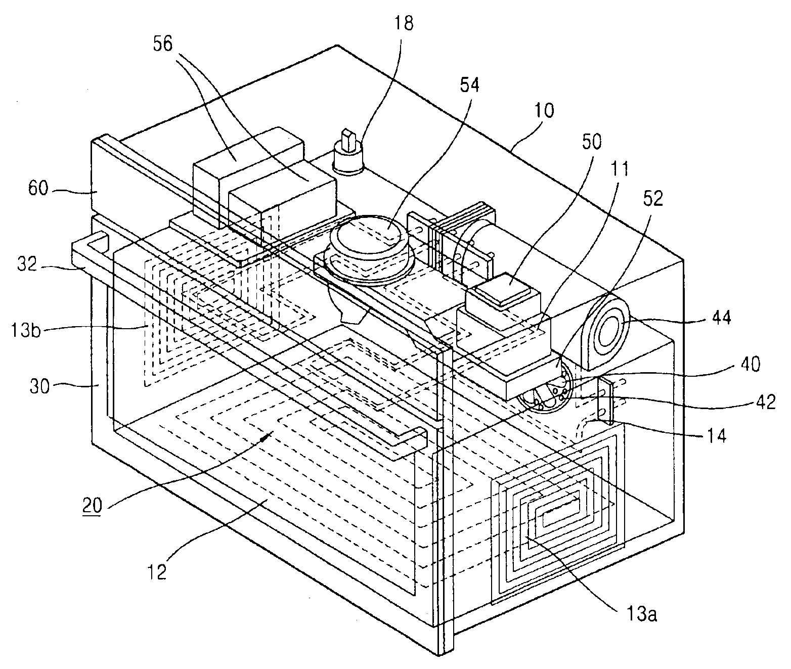
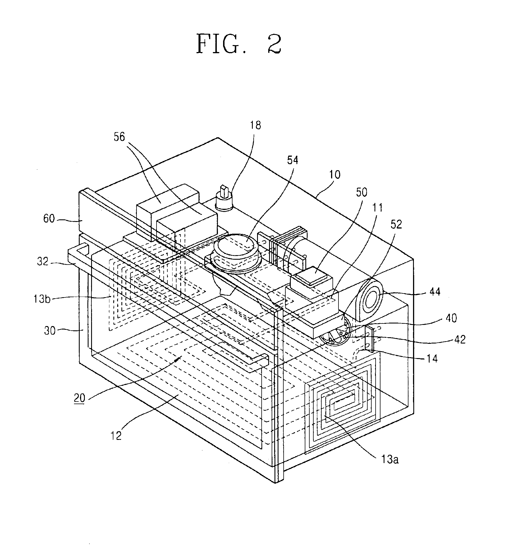
FIG. 2 is a schematic perspective view showing a construction of an electric oven according to one embodiment of the present invention, FIG. 3 is a longitudinal section view showing a position of a heating unit of FIG. 2, and FIG. 4 is a longitudinal section view showing a position of the heating unit of FIG. 2 according to another embodiment.

As shown, an electric oven according to the present invention has a case 10 composed of a plurality of plates, which constitutes an appearance. For example, the electric oven can be composed of a plate for forming a lower surface thereof and cabinets for forming both sides and an upper surface thereof.

A cavity 20 into which food is put and cooking is performed is formed in the case 10. The cavity 20 is formed of a metal having a high thermal conductivity in order to generate heat through an i...


PUM


Abstract

Disclosed is an electric oven which increases temperature fast and reduces heat loss in accordance with that a cavity surface generates its own heat by using an induction heating. The electric oven comprises: a case having a door at a front side and having a cavity for receiving food therein; a magnetron installed at one side of an upper portion of the cavity for generating microwave of high frequency and supplying heat to the cavity; an inverter for generating high frequency at a space between the case and the cavity; first, second, third, and fourth heating units installed each side of the cavity for supplying heat. Since temperature of a cooking chamber can be set as wanted uniformly and faster, preheating time and actual cooking time can be reduced. Also, since inner temperature of the cavity rises faster and simultaneously, an automatic cleaning in the cavity using pyrolysis can be performed faster and uniformly, thereby reducing power consumption.

Description

BACKGROUND OF THE INVENTION1. Field of the InventionThe present invention relates to an electric oven, and more particularly, to an electric oven which increases temperature fast and reduces heat loss in accordance with that a cavity surface generates its own heat by using an induction heating.2. Description of the Related ArtGenerally, an electric oven is a cook used in the kitchen having its own heating means. The electric oven usually cooks food in a cooking chamber by using heat of an electric heater as a heating source, but sometimes uses microwave as a subsidiary heating source by mounting a magnetron.FIG. 1 is a schematic perspective view showing a construction of an electric oven in accordance with the conventional art, in which a heater is mounted as a main heating source, and microwave is used as another heating source.As shown, the conventional electric oven has a case 100 composed of a plurality of plates, which constitutes an appearance. For example, the electric oven c...

Claims


Application Information

Patent Timeline
IPC IPC(8): H05B6/80F24C7/00
CPCH05B6/129H05B6/6488H05B6/6482H05B6/6473F24C7/00
Inventor KIM, WAN-SOOKIM, YANG-KYEONGLEE, YOUNG-MIN
Owner LG ELECTRONICS INC
Why Eureka
Try Eureka